Version : 0.26.09.17 TEST バージョン : 0.26.09.17 TEST
Author : Makoto Kamada 作者 : Makoto Kamada
Website : https://stdkmd.net/xeij/ ウェブサイト : https://stdkmd.net/xeij/
Table of contents目次
- Introductionはじめに
- Recent changes 最近の更新
- Past changes 過去の更新 ▶
- Download ダウンロード
- Install インストール ▶
- Explanation of menu メニューの説明 ▶
- Configuration file 設定ファイル ▶
- Parameters パラメータ ▶
- Source code ソースコード ▶
- Functions and features 機能と特徴 ▶
- About IPLROM 1.6 IPLROM 1.6について ▶
- Explanation of misc/* misc/*の説明 ▶
- Execution examples 実行サンプル ▶
- Try to run the NetBSD/x68k NetBSD/x68kを動かしてみる ▶
- Reference materials 参考資料 ▶
- Link collection リンク集 ▶
- License / Copyright / Disclaimer 使用許諾条件/著作権/免責事項 ▶
- Acknowledgement 謝辞
- Contact information 連絡先
1. Introduction はじめに
XEiJ (X68000 Emulator in Java) is an experimental X68000 emulator written in the Java language. Although XEiJ is an emulator, the sameness to real machines over the details of peripheral circuits is not necessarily top priority. I enjoy thinking new form of X68000 rather than copying old form. When I hit on an idea of an implementation method or a new function, I begin to write a program first of all even if I can not see its entire structure. If the idea goes nowhere, I put it aside until another idea occurs to me. I repeat such things. As a result, many unfinished parts are seen here and there. But I believe that it is meaningful to release XEiJ to the public if any comment in the source code helps someone. XEiJ (X68000 Emulator in Java) は Java 言語で記述された実験的な X68000 エミュレータです。エミュレータといっても周辺回路の隅々まで実機とまったく同じものを作ろうとしているわけではなく、どちらかと言えば X68000 の新しい形を考えることを楽しんでいます。実装方法のアイデアや新しい機能を思い付いたら全体像など見えなくてもとりあえずプログラムを書き始め、詰まったらまた何か湧いてくるまで脇に置いておく、そんなことを繰り返しているので ソースコード は作りかけのところばかりですが、注釈のどれか 1 つでも誰かの役に立つことがあれば公開する意味があると思っています。
2. Recent changes 最近の更新
0.26.09.17 TEST
This is a test version. New features may be substantially changed or removed in the future. これはテスト版です。 新しい機能は今後大幅に変更されるか廃止される可能性があります。
Power Indicator 電源ランプ
Fixed a logic error regarding the power indicator. 電源ランプの論理の誤りを修正しました。
When the power switch is OFF, the power indicator should light up when the RTC ALARM signal is Low; however, it was lighting up when the signal was High. 電源スイッチが OFF のとき、電源ランプは RTC ALARM が Low のとき点灯しなければなりませんが、High のとき点灯していました。
MFP
Fixed the value returned when reading the MFP's TxDR while the timer is running in X68030 mode. X68030 モードで MFP の TxDR をタイマーの動作中に読み出したときの値を修正しました。
On the X68000, the MPU's LDS signal is connected to the MFP's DS pin; since the counter value is transferred to the register every time an instruction is fetched, the current counter value can be read from the TxDR even while the timer is running. In contrast, on the X68030, the YUKI chip's IOLDS signal is connected to the MFP's DS pin; because the counter value is transferred to the register only when an 8-bit port (MFP/RTC/OPM/PCM/FDC/SPC/SCC/PPI/IOI) is accessed, the value read from the TxDR while the timer is running represents a value from some point between the previous read attempt and the current moment. This explains why, when reading the TxDR while the timer is running, a single read suffices on the X68000, whereas two consecutive reads are required on the X68030. X68000 の MFP の DS ピンには MPU の LDS が接続されており、命令を読み出す度にカウンタの値がレジスタへ転送されるので、タイマーの動作中も TxDR からカウンタの現在の値を読み出すことができます。 一方、X68030 の MFP の DS ピンには YUKI の IOLDS が接続されており、8 ビットポート (MFP/RTC/OPM/PCM/FDC/SPC/SCC/PPI/IOI) にアクセスしたときだけカウンタの値がレジスタへ転送されるため、タイマーの動作中に TxDR から読み出される値は前回読み出そうとしたときから現在までのどこかの値になります。 これが、タイマーの動作中に TxDR を読むとき X68000 では 1 回で読めるのに X68030 では 2 回続けて読まなければならない所以です。
In X68030 mode, the time of access to the 8-bit port is recorded to reproduce the garbage data read during the first access. X68030 モードのとき、8 ビットポートにアクセスした時刻を記録することで、1 回目に読み出されるゴミを再現します。
mfpdstest.x
mfpdstest.x has been added. mfpdstest.xを追加しました。
This program verifies whether the DS signal is reflected in the MFP's TCDR. このプログラムは MFP の TCDR に DS が反映されているか確認します。
0.26.09.08
Java version Java のバージョン
As of this writing, the latest version of OpenJDK is 26.0.2.1, and the minimum requirement for Homebrew compatibility is 26. これを書いている時点でOpenJDKの最新版は 26.0.2.1、Homebrewに配慮した最低要件は 26 です。
Power control 電源制御
Power control has been added. 電源制御を追加しました。
You can configure power settings in the power control menu in the file menu. ファイルメニューにある電源制御メニューで電源を設定できます。
Power switch 電源スイッチ
You can configure the state of the power switch. The power switch refers to the vertically oriented switch located in the center of the base of the X680x0 "Twin Tower" unit. The state of the power switch is input to the MFP's I2 pin, and the system detects the act of turning the power switch OFF (High) as a power-off interrupt. 電源スイッチの状態を設定できます。 電源スイッチとは、X680x0 のツインタワーの台座の中央にある縦長のスイッチのことです。 電源スイッチの状態は MFP の I2 ピンに入力されており、電源スイッチを OFF(High) にしたことが電源 OFF 割り込みとしてシステムに検出されます。
The default setting is OFF. This setting is stored in the `powerswitch` parameter. デフォルトは OFF です。 この設定はパラメータ `powerswitch`に保存されます。
External power switch 外部電源スイッチ
You can configure the state of the external power switch. The external power switch refers to a switch connected to the REMOTE terminal on the rear of the unit. The state of the external power switch is combined with the EXPWON signal from the expansion slot and input to the MFP's I1 pin; the system detects the switching of the external power switch to OFF (High) as an external power OFF interrupt. 外部電源スイッチの状態を設定できます。 外部電源スイッチとは、本体背面の REMOTE 端子に接続されたスイッチのことです。 外部電源スイッチの状態は拡張スロットの EXPWON と合流して MFP の I1 ピンに入力されており、外部電源スイッチを OFF(High) にしたことが外部電源 OFF 割り込みとしてシステムに検出されます。
The default setting is OFF. This setting is stored in the `externalswitch` parameter. デフォルトは OFF です。 この設定はパラメータ `externalswitch`に保存されます。
Note that while the external power switch setting can be configured at any time, the actual Compact, X68030, and X68030 Compact units do not have a REMOTE terminal. The Compact and X68030 Compact also lack the EXPWON expansion slot signal, and the MFP's I1 pin is pulled up. なお、外部電源スイッチの状態は常に設定できますが、実機の Compact、X68030、X68030 Compact には REMOTE 端子がありません。Compact と X68030 Compact には拡張スロットの EXPWON もなく、MFP の I1 ピンはプルアップされています。
Power on at startup 開始時に電源を入れる
The power switch can be automatically turned on when starting, regardless of the state at the time of the previous shutdown. 前回終了したときの状態に関わらず、開始するとき自動的に電源スイッチを ON にできます。
The default setting is ON. This setting is stored in the `onatstartup` parameter. デフォルトは ON です。 この設定はパラメータ `onatstartup`に保存されます。
Power off at quit 終了時に電源を切る
When the window's close button or the quit button in the file menu is clicked, the power switch and external power switch are turned off. The program waits for the power-off interrupt routine or the external power-off interrupt routine to shut down the power before terminating. ウインドウのクローズボタンまたはファイルメニューの終了ボタンが押されたとき、電源スイッチと外部電源スイッチが OFF になります。 電源 OFF 割り込みルーチンまたは外部電源 OFF 割り込みルーチンが電源を切るまで待ってから終了します。
The default setting is ON. This setting is stored in the `offatquit` parameter. デフォルトは ON です。 この設定はパラメータ `offatquit`に保存されます。
Wait time 待機時間
You can specify the maximum number of seconds to wait for the power-off interrupt routine or external power-off interrupt routine to turn off the power. 電源 OFF 割り込みルーチンまたは外部電源 OFF 割り込みルーチンが電源を切るまで、最長で何秒待つか指定できます。
The selectable range is 1 to 300 seconds, with a default of 15 seconds. This setting is stored in the `quitwait` parameter. 指定できる範囲は 1~300 秒で、デフォルトは 15 秒です。 この設定はパラメータ `quitwait`に保存されます。
Power indicator 電源ランプ
A rectangle resembling a power indicator is displayed in the menu bar indicator. It appears red when the power is off and green when the power is on. It flashes when the power is being turned off. メニューバーのインジケータに、電源ランプを模した四角形が表示されます。 赤色のときは電源が切れている状態、緑色のときは電源が入っている状態です。 電源を切るとき点滅します。
As of this writing, the RTC alarm function has not yet been implemented. これを書いている時点で RTC のアラーム機能は未実装です。
0.26.08.08
Java version Java のバージョン
As of this writing, the latest version of OpenJDK is 26.0.2, and the minimum requirement for Homebrew compatibility is 26. これを書いている時点でOpenJDKの最新版は 26.0.2、Homebrewに配慮した最低要件は 26 です。
Contrast control コントラストコントロール
Fixed an issue where an ArrayIndexOutOfBoundsException could occur in the contrast control. コントラストコントロールで ArrayIndexOutOfBoundsException が出ることがある不具合を修正しました。
Malfunction screen (experimental) 故障画面 (実験中)
Added the malfunction screen (experimental). 故障画面 (実験中)を追加しました。
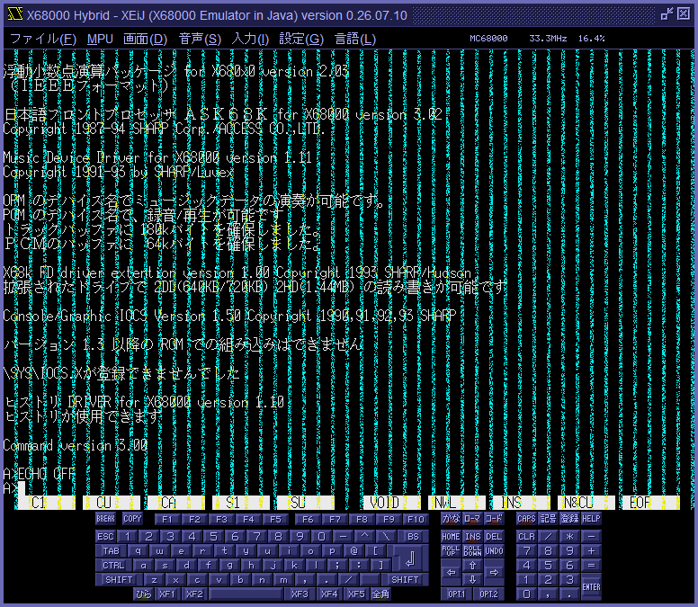
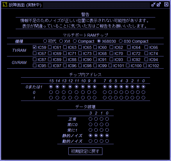
Clinking the malfunction screen (experimental) button in the display menu opens the malfunctin screen (experimental) window. In the malfunction screen (experimental) window, selecting the VRAM chip to fault and the method of data corruption causes noise to appear on the screen. 画面メニューの故障画面 (実験中) ボタンをクリックすると故障画面 (実験中) ウインドウが開きます。 故障画面 (実験中) ウインドウで故障させる VRAM チップとデータの壊し方を選択すると画面にノイズが現れます。
VRAM chip section VRAM チップセクション
Select the VRAM chips to cause to fail. 故障させる VRAM チップを選択します。
I assume that the arrangement of VRAM chips on the schematic and the configuration of the connected signal lines are identical across all models. However, since IC designations vary by model, the display updates to reflect the correct designations when a model is selected. If you happen to have a schematic for a model not listed in the options, I would appreciate it if you could share the sequence of IC designations. 回路図上の VRAM チップの並び順とそこに接続されている信号線の組み合わせは、すべての機種で共通であると推測しています。 しかし IC 番号は機種によって異なるので、機種を選択すると IC 番号の表示が変化するようにしてあります。 選択肢にない機種の回路図をお持ちの方がいらっしゃいましたら、IC 番号の並び順を教えていただけると助かります。
The settings of models and VRAM chips are stored in parameters mlfmodel and mlfchip. 機種と VRAM チップの設定はパラメータmlfmodelとmlfchipに保存されます。
Address within chip section チップ内アドレスセクション
Select the address of the cell to be faulted on a bit-by-bit basis from the following options: either 0 or 1, 0, and 1. This may provide clues not only when specific cells are faulty but also when there is an issue with the address bus. 故障させるセルのアドレスをビット毎に、0 または 1、0、1 から選択します。 一部のセルだけが故障している場合のほか、アドレスバスに問題がある場合もヒントが得られるかも知れません。
The settings of the address within chip are stored in parameters mlfzero and mlfone. チップ内アドレスの設定はパラメータmlfzeroとmlfoneに保存されます。
Data corruption section データ破壊セクション
Select the method for corrupting data on a bit-by-bit basis from the following options: normal, stuck at low, stuck at high, frozen noise, and dynamic noise. When selecting multiple VRAM chips, you can choose a different method of destruction for each of the first four chips. データの壊し方をビット毎に、正常、常に 0、常に 1、静的ノイズ、動的ノイズから選択します。 複数の VRAM チップを選択したとき、1 番目から 4 番目まで異なる壊し方を選択できます。
The settings of the data corruption are stored in parameters mlflow, mlfhigh, mlffrozen and mlfdynamic. データ破壊の設定はパラメータmlflow、mlfhigh、mlffrozenおよびmlfdynamicに保存されます。
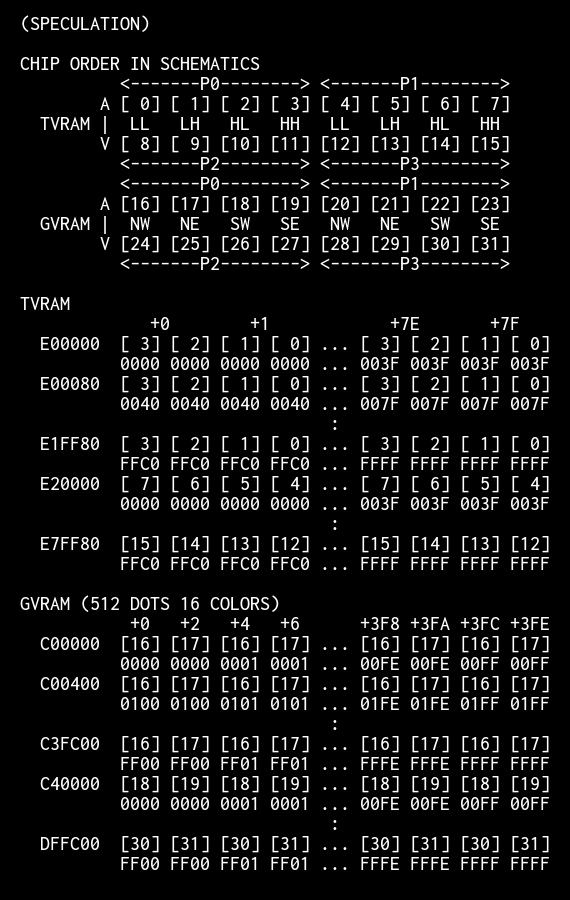
Regarding the address range assigned to each VRAM chip 各 VRAM チップの担当範囲について
I have estimated the address range assigned to each VRAM chip as follows; however, due to a lack of information, there may be errors. If you notice any errors, please provide the correct information. 各 VRAM チップの担当範囲を以下のように推測していますが、情報が不足しており、誤りが含まれている可能性があります。 誤りに気づいた方は情報をお寄せください。
SCSI menu SCSI メニュー
In the SCSI menu, unit numbers 0-15 have been divided into internal SCSI IDs 0-7 and expansion SCSI IDs 0-7. SCSI メニューのユニット番号 0~15 の表示を、内蔵 SCSI ID 0~7 と拡張 SCSI ID 0~7 に分けました。
The parameters `sc0`-`sc15` (used to specify SCSI hard disk image filenames) have been divided into `si0`-`si7` and `se0`-`se7`. `si0`-`si7` are used for image filenames connected to the internal SCSI, while `se0`-`se7` are used for those connected to the expansion SCSI. Although the parameters `sc0`-`sc15` can still be specified, they are remapped to `si0`-`si7` or `se0`-`se7` based on the presence of internal and expansion SCSI interfaces; they are not saved as `sc0`-`sc15`. SCSI ハードディスクのイメージファイル名を指定するパラメータsc0~sc15を、si0~si7とse0~se7に分けました。si0~si7 には内蔵 SCSI に接続するイメージファイル名を、se0~se7 には拡張 SCSI に接続するイメージファイル名を指定します。 パラメータ sc0~sc15 もまだ指定できますが、内蔵 SCSI と拡張 SCSI の有無に合わせて si0~si7 または se0~se7 に読み替えられ、sc0~sc15 としては保存されません。
When setting the boot device to SCSI using the `boot` parameter, specify `sc0`-`sc7` as before. The system automatically selects whether to boot from the internal SCSI or the expansion SCSI at startup. If both internal and expansion SCSI interfaces are present, the expansion SCSI takes precedence, in accordance with Human68k specifications. パラメータbootで起動デバイスを SCSI にするときは、従来通り sc0~sc7 を指定します。 内蔵 SCSI と拡張 SCSI のどちらから起動するかは、起動時に自動的に選択されます。 内蔵 SCSI と拡張 SCSI が両方あるときは、Human68k の仕様に従い、拡張 SCSI が優先されます。
Radio buttons for internal SCSI and expansion SCSI have been added to the Host CD-ROM menu, and the range for the SCSI ID spinner has been changed to 0-7. These settings are saved to the parameters `hcdscsiex` and `hcdscsiid`. ホスト CD-ROM メニューに内蔵 SCSI ラジオボタンと拡張 SCSI ラジオボタンを追加し、SCSI ID スピナーの範囲を 0~7 に変更しました。 これらの設定はパラメータhcdscsiexとhcdscsiidに保存されます。
Text palette テキストパレット
Fixed a bug related to writing bytes to the text palette. The bug was introduced when the flashing lights reduction feature was implemented. (Thanks Antonio Uceda Vera) テキストパレットへのバイト書き込みのバグを修正しました。 点滅光の軽減を導入したときエンバグしていました。(Thanks Antonio Uceda Vera)
FDC
The timing of the Ready interrupt request following motor activation has been changed. モーター ON の後のレディ割り込み要求のタイミングを変更しました。
3. Past changes 過去の更新 ▶
4. Download ダウンロード
- XEiJ_0260917.zip (76800KB)…XEiJ (X68000 Emulator in Java) version 0.26.09.17 TEST
――Read more―――― 続きを読む ―― ――Hide more―――― 続きを隠す ――
- XEiJ_0260908.zip (76698KB)…XEiJ (X68000 Emulator in Java) version 0.26.09.08
- XEiJ_0260808.zip (76663KB)…XEiJ (X68000 Emulator in Java) version 0.26.08.08
- XEiJ_0260708.zip (76455KB)…XEiJ (X68000 Emulator in Java) version 0.26.07.08
- XEiJ_0260608.zip (76362KB)…XEiJ (X68000 Emulator in Java) version 0.26.06.08
- XEiJ_0260508.zip (41505KB)…XEiJ (X68000 Emulator in Java) version 0.26.05.08
- XEiJ_0260408.zip (41470KB)…XEiJ (X68000 Emulator in Java) version 0.26.04.08
- XEiJ_0260308.zip (41428KB)…XEiJ (X68000 Emulator in Java) version 0.26.03.08
- XEiJ_0260208.zip (41413KB)…XEiJ (X68000 Emulator in Java) version 0.26.02.08
- XEiJ_0260108.zip (40969KB)…XEiJ (X68000 Emulator in Java) version 0.26.01.08
- XEiJ_0251208.zip (40877KB)…XEiJ (X68000 Emulator in Java) version 0.25.12.08
- XEiJ_0251108.zip (40797KB)…XEiJ (X68000 Emulator in Java) version 0.25.11.08
- XEiJ_0251008.zip (40774KB)…XEiJ (X68000 Emulator in Java) version 0.25.10.08
- XEiJ_0250908.zip (40752KB)…XEiJ (X68000 Emulator in Java) version 0.25.09.08
- XEiJ_0250808.zip (40489KB)…XEiJ (X68000 Emulator in Java) version 0.25.08.08
- XEiJ_0250708.zip (38737KB)…XEiJ (X68000 Emulator in Java) version 0.25.07.08
- XEiJ_0250608.zip (38034KB)…XEiJ (X68000 Emulator in Java) version 0.25.06.08
5. Install インストール ▶
6. Explanation of menu メニューの説明 ▶
7. Configuration file 設定ファイル ▶
8. Parameters パラメータ ▶
9. Source code ソースコード ▶
10. Functions and features 機能と特徴 ▶
11. About IPLROM 1.6 IPLROM 1.6 について ▶
12. Explanation of misc/* misc/* の説明 ▶
13. Execution examples 実行サンプル ▶
14. Try to run the NetBSD/x68k NetBSD/x68k を動かしてみる ▶
15. Reference materials 参考資料 ▶
16. Link collection リンク集 ▶
17. License / Copyright / Disclaimer 使用許諾条件 / 著作権 / 免責事項 ▶
18. Acknowledgement 謝辞
I would like to thank: Right-holder companies and staffs of the SHARP PRODUCTS USERS FORUM who made efforts to distribute the basic software products of X68000 for free to the public. Keitarou Hiraki and Num Kadoma, they distribute beautiful fonts. Authors of free software that are used as execution examples of XEiJ. Everyone who reported problems and supported XEiJ by warm messages. X68000 の基本的なソフトウェアの無償公開に尽力された権利各社およびシャープ・プロダクツ・ユーザーズ・フォーラムの方々、美しいフォントを公開されている平木敬太郎さん、門真なむさん、実行サンプルとして使わせていただいたフリーソフトウェアの作者の方々、動作報告と応援のメッセージを寄せてくださった皆さん、ありがとうございます。
19. Contact information 連絡先
Makoto Kamada
X
Discord
E-mail メール
