Table of contents目次
- 4096 patterns4096個のパターン
- Adjust to host refresh rateホストのリフレッシュレートに合わせる
- Address translation caches monitorアドレス変換キャッシュモニタ
- Branch log分岐ログ
- F11/F12 and button function assignments window F11/F12およびボタン機能割り当てウインドウ
- CD-ROM
- Control pipe 制御パイプ
-
Core control buttons
コア制御ボタン
- Checkbox to consider ORI.B #$00,D0 as an illegal instruction ORI.B #$00,D0を不当命令とみなすチェックボックス
- Checkbox to stop on error エラーで停止させるチェックボックス
- Checkbox to stop at execution start position 実行開始位置で停止させるチェックボックス
- Break button 停止ボタン
- Trace button トレースボタン
- Trace 10 times button トレース10回ボタン
- Trace 100 times button トレース100回ボタン
- Step button ステップボタン
- Step 10 times button ステップ10回ボタン
- Step 100 times button ステップ100回ボタン
- Step until return button ステップアンティルリターンボタン
- Run button 実行ボタン
- Data break pointデータブレークポイント
- Debug consoleデバッグコンソール
- Disassemble list逆アセンブルリスト
- Edge acceleration縁部加速
- Exclusive mouse mode エクスクルーシブマウスモード
- Extended graphic screen 拡張グラフィック画面
- FC2 pin FC2 ピン
- FE function instructions FE ファンクション命令
- Fixed frequency mode 周波数固定モード
- Fixed load factor mode 負荷率固定モード
- Flashing lights reduction 点滅光の軽減
- Floating point coprocessor board 浮動小数点プロセッサボード
- FLOATn.X rejection FLOATn.X の抑制
- Full pattern memory フルパターンメモリ
- Full specification FPUフルスペック FPU
- GIF animation recording GIFアニメーション録画
- High memory on 060turbo 060turboのハイメモリ
- High memory on X68030/Xellent30 X68030/Xellent30のハイメモリ
- Host CD-ROM ホストCD-ROM
- Host file system ホストファイルシステム
- IPLROM 1.6
- Java language Java言語
- Key assignments window キー割り当てウインドウ
- Logical space monitor論理空間モニタ
- MEGA DRIVE 3 button padメガドラ 3 ボタンパッド
- MEGA DRIVE 6 button padメガドラ 6 ボタンパッド
- Memory dump listメモリダンプリスト
- Mercury-Unit V4 (MK-MU1) Mercury-Unit V4 (MK-MU1)
- Model 機種
- Mother board coprocessorマザーボードコプロセッサ
- Normal 2 button padノーマル 2 ボタンパッド
- Number of spritesスプライトの枚数
- OPM logOPMログ
- Palette viewer window パレットビュアウインドウ
- Paste貼り付け
- Paste pipe 貼り付けパイプ
- PCM interpolation algorithmPCM 補間アルゴリズム
- Physical space monitor物理空間モニタ
- Printerプリンタ
- Program flow visualizerプログラムフロービジュアライザ
- Raster break pointラスタブレークポイント
- Register list レジスタリスト
- Root pointer listルートポインタリスト
- Rounded corner adjustment 角丸調整
- Row and column scroll 行スクロールと列スクロール
- RS-232C and terminal window RS-232Cとターミナルウインドウ
- Scanline effect 走査線エフェクト
- Screen mode test window表示モードテストウィンドウ
- Screen rotation 画面の回転
- Seamless mouse mode シームレスマウスモード
- Shiromadokun emulator 白窓君エミュレータ
- Sound interpolation algorithm音声補間アルゴリズム
- Sound monitor音声モニタ
- Source oscillator frequency原発振周波数
- BG1 displayed in 512x512512x512でBG1を表示
- Sprites displayed in 768x512768x512でスプライトを表示
- Sprite pattern viewer window スプライトパターンビュアウインドウ
- Stereoscopic viewing 立体視
- Text screen copy テキスト画面コピー
- Triple precision floating point number三倍精度浮動小数点数
- CYBER STICK サイバースティック
- XInput support XInput対応
- Z keyboard support Zキーボード対応
1. 4096 patterns 4096 個のパターン
If the 4096 patterns checkbox in the modification menu is checked and reset, 4096 patterns can be defined. 改造メニューの4096 個のパターンチェックボックスを ON にしてリセットすると、4096 個のパターンを定義できるようになります。
This setting is stored in the parameter sprbank. この設定はパラメータ sprbankに保存されます。
Text area shift テキストエリアの移動
Shift the text area from $00EBC000-$00EBFFFF to $00EB4000-$00EB7FFF so that you can define 256 patterns even if you use 2 planes of text area. テキストエリアを $00EBC000~$00EBFFFF から $00EB4000~$00EB7FFF へ移動させて、テキストエリアを 2 面使っていてもパターンを 256 個定義できるようにします。
| Addressアドレス | Before text area shiftテキストエリアの移動前 | After text area shiftテキストエリアの移動後 | ||||
|---|---|---|---|---|---|---|
| 256x256/512x512 | 768x512 | 256x256/512x512 | 768x512 | |||
| $00EB0000 : $00EB03FF | Sprite 0 to 127スプライト 0~127 | Bus errorバスエラー | Sprite 0 to 127スプライト 0~127 | Bus errorバスエラー | ||
| $00EB0400 : $00EB07FF | Sprite 128 to 255 (extended)スプライト 128~255(拡張) | Sprite 128 to 255 (extended)スプライト 128~255(拡張) | ||||
| $00EB0800 : $00EB0815 | Control registers制御レジスタ | |||||
| $00EB0816 : $00EB3FFF | Unused未使用 | |||||
| $00EB4000 : $00EB5FFF | Unused未使用 | Text area 0テキストエリア 0 | Bus errorバスエラー | |||
| $00EB6000 : $00EB7FFF | Text area 0テキストエリア 1 | |||||
| $00EB8000 : $00EBBFFF | Pattern 0 to 127パターン 0~127 | Bus errorバスエラー | Pattern 0 to 255パターン 0~255 | |||
| $00EBC000 : $00EBDFFF | Pattern 128 to 191パターン 128~191 | Text area 0テキストエリア 0 | ||||
| $00EBE000 : $00EBFFFF | Pattern 192 to 255パターン 192~255 | Text area 1テキストエリア 1 | Text area 1テキストエリア 1 | |||
Referencing patterns from sprite and text areas スプライトエリアとテキストエリアからのパターンの参照
Increase the number of patterns that can be referenced from 256 to 1024 or 4096 by changing the sprite and text areas as follows
スプライトエリアとテキストエリアを以下のように変更することで、参照できるパターンの数を 256 個から 1024 個または 4096 個に増やします。
| 15 | 14 | 13 | 12 | 11 | 10 | 9 | 8 | 7 | 6 | 5 | 4 | 3 | 2 | 1 | 0 | |
|---|---|---|---|---|---|---|---|---|---|---|---|---|---|---|---|---|
| +0 | X 座標 | |||||||||||||||
| +2 | Y 座標 | |||||||||||||||
| +4 | Up/Down上下 | Left/Right左右 | Palette blockパレットブロック | Pattern numberパターン番号 | ||||||||||||
| +6 | Tofu豆腐 | Priorityプライオリティ | ||||||||||||||
| : | ||||||||||||||||
| 15 | 14 | 13 | 12 | 11 | 10 | 9 | 8 | 7 | 6 | 5 | 4 | 3 | 2 | 1 | 0 | |
|---|---|---|---|---|---|---|---|---|---|---|---|---|---|---|---|---|
| +0 | X 座標 | |||||||||||||||
| +2 | Y 座標 | |||||||||||||||
| +4 | Up/Down上下 | Left/Right左右 | Bank numberバンク番号 | Palette blockパレットブロック | Pattern numberパターン番号 | |||||||||||
| +6 | Tofu豆腐 | Priorityプライオリティ | ||||||||||||||
| : | ||||||||||||||||
| 15 | 14 | 13 | 12 | 11 | 10 | 9 | 8 | 7 | 6 | 5 | 4 | 3 | 2 | 1 | 0 | |
|---|---|---|---|---|---|---|---|---|---|---|---|---|---|---|---|---|
| +0 | X 座標 | |||||||||||||||
| +2 | Y 座標 | |||||||||||||||
| +4 | Bank numberバンク番号 | Palette blockパレットブロック | Pattern numberパターン番号 | |||||||||||||
| +6 | Up/Down上下 | Left/Right左右 | Tofu豆腐 | Priorityプライオリティ | ||||||||||||
| : | ||||||||||||||||
| 15 | 14 | 13 | 12 | 11 | 10 | 9 | 8 | 7 | 6 | 5 | 4 | 3 | 2 | 1 | 0 |
|---|---|---|---|---|---|---|---|---|---|---|---|---|---|---|---|
| Up/Down上下 | Left/Right左右 | Palette blockパレットブロック | Pattern numberパターン番号 | ||||||||||||
| : | |||||||||||||||
| 15 | 14 | 13 | 12 | 11 | 10 | 9 | 8 | 7 | 6 | 5 | 4 | 3 | 2 | 1 | 0 |
|---|---|---|---|---|---|---|---|---|---|---|---|---|---|---|---|
| Up/Down上下 | Left/Right左右 | Bank numberバンク番号 | Palette blockパレットブロック | Pattern numberパターン番号 | |||||||||||
| : | |||||||||||||||
| 15 | 14 | 13 | 12 | 11 | 10 | 9 | 8 | 7 | 6 | 5 | 4 | 3 | 2 | 1 | 0 |
|---|---|---|---|---|---|---|---|---|---|---|---|---|---|---|---|
| Bank numberバンク番号 | Palette blockパレットブロック | Pattern numberパターン番号 | |||||||||||||
| : | |||||||||||||||
When the number of patterns is increased to 4096, the up/down and left/right inversions are eliminated. However, if there is no need to save patterns, it is considered sufficient to define inverted patterns as needed. 4096 個にしたとき上下左右の反転がなくなりますが、パターンを節約する必要がなければ、必要に応じて反転したパターンを定義すればよいと考えられます。
Replacing the inversion instructions with a bank selection allows you to define the result of the inversion. For example, shadows of patterns that used to be done by inversion can be adjusted simply by changing the definition process. 反転の指示をバンク選択に置き換えることで、反転の結果を定義できるようになります。例えば、反転で済ませていたパターンの影の調整が、定義の処理の変更だけで行えます。
Expansion of pattern area パターンエリアの拡張
The pattern area ($00EB8000-$00EBFFFF) is expanded 16 times using bank switching, increasing the number of patterns that can be defined from 256 to 4096. パターンエリア ($00EB8000~$00EBFFFF) をバンク切り替えを用いて 16 倍に拡張することで、定義できるパターンの数を 256 個から 4096 個に増やします。
The weakness of bank switching is random access, but since a pattern is 16 or 64 words, even if writes increase by one word per pattern, the impact is expected to be limited. バンク切り替えの弱点はランダムアクセスですが、1 パターンが 16 または 64 ワードなので、書き込みが 1 パターンあたり 1 ワード増えたとしても影響は限定的と考えられます。
Adding registers レジスタの追加
Added bank control register ($00EB0812) and bank select register ($00EB0814). バンク制御レジスタ ($00EB0812) とバンク選択レジスタ ($00EB0814) を追加します。
| 15 | 14 | 13 | 12 | 11 | 10 | 9 | 8 | 7 | 6 | 5 | 4 | 3 | 2 | 1 | 0 |
|---|---|---|---|---|---|---|---|---|---|---|---|---|---|---|---|
| Modeモード | Shift移動 | ||||||||||||||
| Modeモード | Number of patternsパターンの数 | Sprite inversionスプライトの反転 | Text inversionテキストの反転 |
|---|---|---|---|
| 0 | 256 | Availableできる | |
| 1 | 1024 | ||
| 2 | 4096 | Not availableできない | |
| 3 | Availableできる | Not availableできない | |
| Shift移動 | Text area shiftテキストエリアの移動 | Range of the text areaテキストエリアの範囲 |
|---|---|---|
| 0 | Not doしない | $00EBC000-$00EBFFFF$00EBC000~$00EBFFFF |
| 1 | Doする | $00EB4000-$00E7FFFF$00EB4000~$00EB7FFF |
| 15 | 14 | 13 | 12 | 11 | 10 | 9 | 8 | 7 | 6 | 5 | 4 | 3 | 2 | 1 | 0 |
|---|---|---|---|---|---|---|---|---|---|---|---|---|---|---|---|
| Bank numberバンク番号 | |||||||||||||||
| Bank numberバンク番号 | Range of pattern numbers accessible in $00EB8000-$00EBFFFF$00EB8000~$00EBFFFF でアクセスできるパターン番号の範囲 |
|---|---|
| 0 | 0 to 255†0~255† |
| 1 | 256 to 511256~511 |
| 2 | 512 to 767512~767 |
| 3 | 768 to 1023768~1023 |
| 4 | 1024 to 12791024~1279 |
| 5 | 1280 to 15351280~1535 |
| 6 | 1536 to 17911536~1791 |
| 7 | 1792 to 20471792~2047 |
| 8 | 2048 to 23032048~2303 |
| 9 | 2304 to 25592304~2559 |
| 10 | 2560 to 28152560~2815 |
| 11 | 2816 to 30712816~3071 |
| 12 | 3072 to 33273072~3327 |
| 13 | 3328 to 35833328~3583 |
| 14 | 3584 to 38393584~3839 |
| 15 | 3840 to 40953840~4095 |
†The number of patterns that can be accessed in bank 0 is 256, but if one plane is used without text area shift, the number is reduced to 192, and if two planes are used, the number is reduced to 128. †バンク 0 でアクセスできるパターンは 256 個ですが、テキストエリアを移動せず 1 面使うと 192 個に、同じく 2 面使うと 128 個に減ります。
Pattern numbers from 0 to 4095 can be written to the bank select register without shifting. 0~4095 のパターン番号をシフトせずにバンク選択レジスタへ書き込めます。
To prevent later programs from malfunctioning, set both back to 0 when you are finished using them. 後のプログラムが誤動作しないように、どちらも使い終わったら 0 に戻してください。
Pseudo graphic screen 疑似グラフィック画面
By laying each of the 4096 patterns in the background one by one, it can be used as a third 1024x1024 dot 16-color graphic screen. バックグラウンドに 4096 個のパターンを 1 個ずつ敷き詰めることで、3 枚目の 1024x1024 ドット 16 色のグラフィック画面として使うことができます。
Supplemental information on text area テキストエリアに関する補足
The text area before shift and the second half of bank 0 in the pattern area have the same address but different entities. Data written to the text area before shift is written to both the text area and the second half of bank 0. Data read from the text area before shift is read from the second half of bank 0. Data written to the text area after shift cannot be read from the text area before shift because it has not been written to the second half of bank 0. 移動前のテキストエリアと、パターンエリアのバンク 0 の後半は、アドレスが同じですが実体が違います。移動前のテキストエリアへ書き込んだデータは、テキストエリアと、バンク 0 の後半の両方へ書き込まれます。移動前のテキストエリアから読み出したデータは、バンク 0 の後半から読み出されます。移動後のテキストエリアへ書き込んだデータは、バンク 0 の後半へ書き込まれていないので、移動前のテキストエリアから読み出せません。
When bank 1 or higher is selected, the text area before shift will not be visible. バンク 1 以上を選択すると、移動前のテキストエリアは見えなくなります。
Other その他
Standard IOCS calls do not support 4096 patterns. 標準の IOCS コールは 4096 個のパターンに対応していません。
2. Adjust to host refresh rate ホストのリフレッシュレートに合わせる
Adjust VSYNC frequency to the host refresh rate. When the adjust to host refresh rate checkbox in the modification menu is ON, the dot clock frequency is adjusted so that they match if the host refresh rate is 0.75 to 1.25 times the vertical sync frequency. Changes will take effect immediately. This setting is saved in the parameter adjustvsync. 垂直同期周波数をホストのリフレッシュレートに合わせます。 改造メニューのホストのリフレッシュレートに合わせるチェックボックスが ON のとき、ホストのリフレッシュレートが垂直同期周波数の 0.75~1.25 倍ならばそれらが一致するようにドットクロック周波数を調整します。 変更は直ちに反映されます。 この設定はパラメータ adjustvsyncに保存されます。
The host refresh rate text field in the modification menu allows you to specify the host refresh rate. If not specified, DisplayMode.getRefreshRate() is used to try to get the refresh rate. If it is not specified and cannot be obtained, 59.94 Hz is used. Changes will take effect immediately. This setting is saved in the parameter refreshrate. 改造メニューのホストのリフレッシュレートテキストフィールドでホストのリフレッシュレートを指定できます。 指定がないときは DisplayMode.getRefreshRate() を用いてリフレッシュレートの取得を試みます。 指定がなく取得もできなかったときは 59.94Hz を使用します。 変更は直ちに反映されます。 この設定はパラメータ refreshrateに保存されます。
The current vertical sync frequency can be checked with the screen mode test window. 現在の垂直同期周波数は表示モードテストウィンドウで確認できます。
To quickly check the effect, use "echo ^[[?4h" (for ^[, press the ESC key twice) to put the console in 8-dot smooth scroll mode and then display a long text file. If you do not match the refresh rate of the host, the scrolling will rattle, but if you do, the scrolling will be smooth. If you set "mew d0a 1" in db.x to 4-dot smooth scroll mode, the smoothness will increase. 手っ取り早く効果を確認するには、「echo ^[[?4h」(^[は ESC キーを 2 回押す) でコンソールを 8 ドットスムーススクロールモードにしてから長いテキストファイルを表示するとよいでしょう。 ホストのリフレッシュレートに合わせないとガタガタとスクロールしますが、合わせるとスムースにスクロールします。db.x で「mew d0a 1」として 4 ドットスムーススクロールモードにするとヌルヌル感が増します。
3. Address translation caches monitor アドレス変換キャッシュモニタ
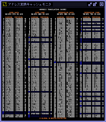
Address translation caches monitor displays contents of the address translation caches of MMU. The address translation caches of XEiJ are an original specification different from MC68060. アドレス変換キャッシュモニタは MMU のアドレス変換キャッシュの内容を表示します。XEiJ のアドレス変換キャッシュは MC68060 と異なる独自仕様です。
4. Branch log 分岐ログ
XEiJ saves the branch target address and the branch source address of the latest 65536 branches in the branch log. Branches mentioned here include all non-incremental changes of program counter such as interrupts. You can trace back changes of program counter and disassemble codes at the branch source address. XEiJ はプログラムカウンタのインクリメント以外の変化すなわち割り込みを含むすべての分岐の分岐元と分岐先のアドレスを直近の 65535 回までメモリ上の分岐ログに保存しています。分岐ログウインドウを開くとプログラムカウンタの変化を遡って逆アセンブルすることができます。
Core control buttons are located. コア制御ボタンが配置されています。
5. F11/F12 and button function assignments window F11/F12 およびボタン機能割り当てウインドウ
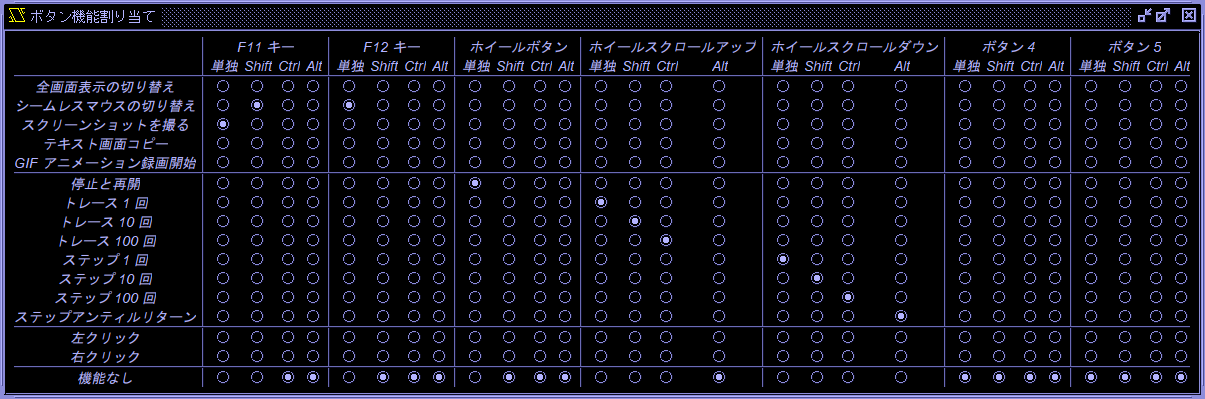
Clicking F11/F12 and button function assignments in the input menu opens the F11/F12 and button function assignments window. In the button function assignments window, you can assign functions to the F11 key, F12 key, wheel button, wheel scroll up, wheel scroll down, button 4, and button 5. The F11 and F12 keys can be used to separate functions for normal and fullscreen display. You can select one of Shift, Ctrl, or Alt as a modifier key. 入力メニューのF11/F12 およびボタン機能割り当てをクリックすると F11/F12 およびボタン機能割り当てウインドウが開きます。 ボタン機能割り当てウインドウで、F11 キー、F12 キー、ホイールボタン、ホイールスクロールアップ、ホイールスクロールダウン、ボタン 4、ボタン 5 に機能を割り当てることができます。F11 キーと F12 キーは通常表示のときと全画面表示のときで機能を分けられます。 修飾キーとして Shift、Ctrl、Alt から 1 個を選択できます。
The functions that can be assigned to each button are as follows. 各ボタンに割り当てられる機能は以下の通りです。
- Toggle fullscreen 全画面表示の切り替え
- Toggle seamless mouse シームレスマウスの切り替え
- Take a screenshot スクリーンショットを撮る
- Text screen copy テキスト画面コピー
- Start recording GIF animation GIF アニメーション録画開始
- Stop and start 停止と再開
- 1 trace トレース 1 回
- 10 traces トレース 10 回
- 100 traces トレース 100 回
- 1 step ステップ 1 回
- 10 steps ステップ 10 回
- 100 steps ステップ 100 回
- Step until return ステップアンティルリターン
- Left click 左クリック
- Right click 右クリック
- No function 機能なし
These settings are stored in parameter f11key, etc. The parameter keys are strings consisting of shift, ctrl, alt, which represent modifier keys, and f11key, fullscreenf11key, f12key, fullscreenf12key, wheel, wheelup, wheeldown, button4, button5, which represent buttons. The parameter values represent the corresponding functions. これらの設定はパラメータ f11key などに保存されます。 パラメータのキーは修飾キーを表す shift、ctrl、alt と、ボタンを表す f11key、fullscreenf11key、f12key、fullscreenf12key、wheel、wheelup、wheeldown、button4、button5 を連結した文字列です。 パラメータの値は対応する機能を表します。
The F11 and F12 keys can only be entered with the keys assigned in the key assignments window when the no function is selected in the F11/F12 and button function assignments window. F11 キーと F12 キーはF11/F12 およびボタン機能割り当てウインドウで機能なしを選択したときだけキー割り当てウインドウで割り当てたキーを入力できます。
6. CD-ROM
ISO files are accessed as if they are SCSI CD-ROM drives. In X68000 Hybrid, X68030 and 060turbo mode, you can boot the system from an ISO file by clicking "Reboot from it" button if a boot sector exists. Files in CD-ROM are accessed via susie.x in Human68k environment. *.ISO ファイルを SCSI CD-ROM とみなします。ブートセクタがあるときは「ここから再起動」で CD-ROM から直接起動できます。Human68k からは susie.x でアクセスできます。
7. Control pipe 制御パイプ
When the paste and control pipe checkbox in the pipe settings menu is turned on, you can send control commands such as pressing the interrupt switch from other processes to XEiJ via the control pipe. This setting is saved in the parameter pipeencoding. The name of the control pipe is \\.\pipe\XEiJControl on Windows and /tmp/XEiJControl on WSL (Ubuntu). パイプ設定メニューにある貼り付けおよび制御パイプチェックボックスが ON のとき、制御パイプを介して他のプロセスから XEiJ へインタラプトスイッチを押すなどの制御コマンドを送信できます。 制御パイプの名前は Windows のとき \\.\pipe\XEiJControl、WSL (Ubuntu) のとき /tmp/XEiJControl です。 この設定はパラメータ pipeencodingに保存されます。
You can select the character encoding for the pipe using the SJIS radio button and UTF-8 radio button in the pipe settings menu. The default is SJIS. The change takes effect immediately. This setting is saved in the parameter pipeencoding. パイプ設定メニューの SJIS ラジオボタンと UTF-8 ラジオボタンでパイプの文字コードを選択できます。 デフォルトは SJIS です。 変更は直ちに反映されます。 この設定はパラメータ pipeencodingに保存されます。
>echo interrupt > \\.\pipe\XEiJControl
| control command制御コマンド | function機能 |
|---|---|
| interrupt | press the interrupt switchインタラプトスイッチを押す |
| presskey keyname ... | press keysキーを押す |
| releasekey keyname ... | release keysキーを離す |
| reset | press the reset switchリセットスイッチを押す |
| typekey keyname ... | type keysキーを押して離す |
| key nameキーの名前 | scan codeスキャンコード | note備考 |
|---|---|---|
| ESC | 1 | |
| 1 | 2 | |
| 2 | 3 | |
| 3 | 4 | |
| 4 | 5 | |
| 5 | 6 | |
| 6 | 7 | |
| 7 | 8 | |
| 8 | 9 | |
| 9 | 10 | |
| 0 | 11 | |
| MINUS | 12 | - |
| CARET | 13 | |
| YEN | 14 | \ |
| BS | 15 | |
| TAB | 16 | |
| Q | 17 | |
| W | 18 | |
| E | 19 | |
| R | 20 | |
| T | 21 | |
| Y | 22 | |
| U | 23 | |
| I | 24 | |
| O | 25 | |
| P | 26 | |
| AT | 27 | @ |
| LEFTBRACKET | 28 | [ |
| RETURN | 29 | |
| A | 30 | |
| S | 31 | |
| D | 32 | |
| F | 33 | |
| G | 34 | |
| H | 35 | |
| J | 36 | |
| K | 37 | |
| L | 38 | |
| SEMICOLON | 39 | ; |
| COLON | 40 | : |
| RIGHTBRACKET | 41 | ] |
| Z | 42 | |
| X | 43 | |
| C | 44 | |
| V | 45 | |
| B | 46 | |
| N | 47 | |
| M | 48 | |
| COMMA | 49 | , |
| PERIOD | 50 | |
| SLASH | 51 | |
| UNDERLINE | 52 | |
| SPACE | 53 | |
| HOME | 54 | |
| DEL | 55 | |
| ROLLUP | 56 | |
| ROLLDOWN | 57 | |
| UNDO | 58 | |
| LEFT | 59 | ← |
| UP | 60 | ↑ |
| RIGHT | 61 | → |
| DOWN | 62 | ↓ |
| CLR | 63 | |
| TENKEYSLASH | 64 | テンキー / |
| TENKEYASTERISK | 65 | テンキー * |
| TENKEYMINUS | 66 | テンキー - |
| TENKEY7 | 67 | |
| TENKEY8 | 68 | |
| TENKEY9 | 69 | |
| TENKEYPLUS | 70 | テンキー + |
| TENKEY4 | 71 | |
| TENKEY5 | 72 | |
| TENKEY6 | 73 | |
| TENKEYEQUAL | 74 | テンキー = |
| TENKEY1 | 75 | |
| TENKEY2 | 76 | |
| TENKEY3 | 77 | |
| ENTER | 78 | |
| TENKEY0 | 79 | |
| TENKEYCOMMA | 80 | テンキー , |
| TENKEYPERIOD | 81 | テンキー . |
| KIGOU | 82 | 記号入力 |
| TOUROKU | 83 | 登録 |
| HELP | 84 | |
| XF1 | 85 | |
| XF2 | 86 | |
| XF3 | 87 | |
| XF4 | 88 | |
| XF5 | 89 | |
| KANA | 90 | かな |
| ROMA | 91 | ローマ字 |
| CODE | 92 | コード入力 |
| CAPS | 93 | |
| INS | 94 | |
| HIRAGANA | 95 | ひらがな |
| ZENKAKU | 96 | 全角 |
| BREAK | 97 | |
| COPY | 98 | |
| F1 | 99 | |
| F2 | 100 | |
| F3 | 101 | |
| F4 | 102 | |
| F5 | 103 | |
| F6 | 104 | |
| F7 | 105 | |
| F8 | 106 | |
| F9 | 107 | |
| F10 | 108 | |
| SHIFT | 112 | |
| CTRL | 113 | |
| OPT1 | 114 | OPT.1 |
| OPT2 | 115 | OPT.2 |
| NUM | 116 |
8. Core control buttons コア制御ボタン
Common core control buttons are located in the branch log, disassemble list, and register list. 分岐ログ、逆アセンブルリスト、レジスタリストに共通のコア制御ボタンが配置されています。
-
 …Checkbox to consider ORI.B #$00,D0 as an illegal instruction …ORI.B #$00,D0 を不当命令とみなすチェックボックス
 -
 …Checkbox to stop on error … エラーで停止させるチェックボックス
 -
 …Checkbox to stop at execution start position … 実行開始位置で停止させるチェックボックス
 -
 …Break button … 停止ボタン
 -
 …Trace button … トレースボタン
 -
 …Trace 10 times button … トレース 10 回ボタン
 -
 …Trace 100 times button … トレース 100 回ボタン
 -
 …Step button … ステップボタン
 -
 …Step 10 times button … ステップ 10 回ボタン
 -
 …Step 100 times button … ステップ 100 回ボタン
 -
 …Step until return button … ステップアンティルリターンボタン
 -
 …Run button … 実行ボタン
8.1. Checkbox to consider ORI.B #$00,D0 as an illegal instruction ORI.B #$00,D0 を不当命令とみなすチェックボックス
Consider ORI.B #$00,D0 as an illegal instruction. The instruction code for ORI.B #$00,D0 is $0000,$0000. This instruction is rarely written intentionally, but is often executed when a runaway condition occurs with a jump to an unintended address. By treating this as an illegal instruction, it makes it easier for the debugger to catch the runaway. If the runaway is caught at an early stage, it is expected to reduce the time and effort required to find the cause of the problem. ORI.B #$00,D0 を不当命令とみなします。ORI.B #$00,D0 の命令コードは $0000,$0000 です。 この命令は意図して書かれることはほとんどありませんが、意図しないアドレスにジャンプして暴走したときにしばしば実行されます。 これを不当命令とみなすことで、デバッガで暴走を捕捉しやすくします。 暴走を早い段階で捉えられれば、原因を探る手間が減ることが期待できます。
8.2. Checkbox to stop on error エラーで停止させるチェックボックス
The core is stopped when a bus error, address error, illegal instruction, divide by zero, CHK instruction, TRAPV instruction, or privilege violation occurs. If an abnormality is caught at an early stage, it is expected to reduce the time and effort required to find the cause. A bus error intentionally generated to check for the presence of an expansion board will also stop the system. バスエラー、アドレスエラー、不当命令、ゼロ除算、CHK 命令、TRAPV 命令、特権違反などが発生したらコアを停止させます。 異常を早い段階で捉えられれば、原因を探る手間が減ることが期待できます。 拡張ボードの有無を確認するために意図的に発生させられたバスエラーでも停止します。
8.3. Checkbox to stop at execution start position 実行開始位置で停止させるチェックボックス
Stops the core at the start of program execution. It is used when you want to set a breakpoint in a program before executing it. The disassemble list shows the name of the program and the offset from the beginning, so you can easily find the place to set a breakpoint by comparing it with the assembly list generated by HAS060.X and the disassembly list generated by dis.x. This feature is only available when Human68k 3.02 is running. プログラムの実行開始位置でコアを停止させます。 プログラムにブレークポイントを仕掛けてから実行したいときに使います。 逆アセンブルリストにはプログラムの名前と先頭からのオフセットが表示されるので、HAS060.Xが生成したアセンブルリストやdis.xが生成した逆アセンブルリストと照合することで、ブレークポイントを仕掛ける場所を簡単に見つけられます。 この機能は Human68k 3.02 が動作しているときだけ有効です。
8.4. Break button 停止ボタン
Stops the core. All peripheral circuits as well as the MPU will stop. The cursor will also stop blinking, but this is not abnormal. Note that the RTC is based on the platform time and does not stop. In programs that use the RTC to measure time, the time the core was stopped is included in the elapsed time. コアを停止させます。MPU だけでなく周辺回路もすべて止まります。 カーソルの点滅も止まりますが異常ではありません。RTC はプラットフォームの時刻を基準にしているので止まらないことに注意してください。RTC を使って時間を計るプログラムではコアが止まっていた時間も経過時間に含まれます。
8.5. Trace button トレースボタン
Trace execution is performed. Trace execution executes the instruction pointed to by the program counter. It can trace areas that cannot be traced by the DB.X trace command, such as inside raster interrupt routines. トレース実行を行います。 トレース実行は、プログラムカウンタが指す命令を実行します。 ラスタ割り込みルーチンの中などの DB.X のトレースコマンドではトレースできない領域もトレースできます。
8.6. Trace 10 times button トレース 10 回ボタン
Repeat trace execution 10 times. トレース実行を 10 回繰り返します。
8.7. Trace 100 times button トレース 100 回ボタン
Repeat trace execution 100 times. トレース実行を 100 回繰り返します。
8.8. Step button ステップボタン
Step execution is performed. Step execution executes the instruction pointed to by the program counter if it is a branch instruction, or else it places a temporary breakpoint immediately after the instruction and executes up to that point. Subroutine calls, DOS calls, IOCS calls, etc. do not stop until they return. ステップ実行を行います。 ステップ実行は、プログラムカウンタが指す命令が分岐命令ならばそれを実行し、さもなくばその命令の直後に臨時のブレークポイントを置いてそこまで実行します。 サブルーチン呼び出し、DOS コール、IOCS コールなどは復帰するまで止まりません。
8.9. Step 10 times button ステップ 10 回ボタン
Repeat step execution 10 times. ステップ実行を 10 回繰り返します。
8.10. Step 100 times button ステップ 100 回ボタン
Repeat step execution 100 times. ステップ実行を 100 回繰り返します。
8.11. Step until return button ステップアンティルリターンボタン
Step execution is repeated until an attempt is made to execute a return instruction with the stack pointer not decremented. スタックポインタが減っていない状態で復帰命令を実行しようとするまで、ステップ実行を繰り返します。
8.12. Run button 実行ボタン
Unstops the core. コアの停止を解除します。
9. Data break point データブレークポイント
MPU stops just after it reads or writes data in the specified range at the specified physical address. Data break point shows its power in the following case: "You know that the direct cause of malfunction of the program is broken code or data. But you do not know when and who broke them." You can catch directly the instruction that destroyed code or data by placing a data break point. When you think that the instruction is not written with the intention and the program runs away, trace the branch-log back to an instruction that has additional information such as a device name or an executable file name. If a copied data was broken, put a data break point at the copy source. You will efficiently find the root of the problem. 特定の物理アドレスで特定の範囲のデータの読み書きを行った命令の直後で MPU を停止させます。「プログラムの誤動作の直接的な原因がコードやデータが破壊されているためであることは分かったけれど、いつ誰が壊したのか分からない」というときにデータブレークポイントが威力を発揮します。データブレークポイントを使えばコードやデータを破壊した命令を直接捉えることができます。その命令が正しく記述されたものではなく暴走していると思われる場合は 分岐ログ を使って 逆アセンブルリスト で近くにデバイス名または実行ファイル名が表示されるところまで遡ります。別の場所からコピーされたデータが壊れていたときはコピー元にデータブレークポイントを仕掛けます。効率よく問題の大元を見つけることができるでしょう。
9.1. Mechanism of the data break point データブレークポイントの仕組み
Memory map of XEiJ is an array of memory mapped devices. Each page size is 8KB. Data break point device, which is an indirect memory mapped device, is assigned to the page that has data break points. When MPU reads or writes the page, data break point device invokes previous memory mapped device and stops MPU if the stop conditions are satisfied. An advantage of this method is its lightness. If a data break point starts monitoring all bus access, overall performance will significantly decrease. However, by using an indirect memory mapped device, overhead at a page that has no data break point becomes always zero even if you put several hundred data break points on other pages. There are some defects of this method. Misaligned accesses are not able to be detected because MPU splits them before bus access. In multi-task environment, code and data on RAM that physical address is not fixed are not able to be monitored. XEiJ のメモリマップはメモリマップトデバイスの配列です。データブレークポイントが設定されたページには間接メモリマップトデバイスであるデータブレークポイントデバイスが割り当てられ、データブレークポイントデバイスが元のメモリマップトデバイスを呼び出して停止条件が成立していたら MPU を止めます。この方法の利点は軽量であることです。データブレークポイントを 1 個設定しただけですべてのバスアクセスの監視が始まったのでは全体のパフォーマンスが大幅に低下してしまいますが、この方法ならばデータブレークポイントを何百個設定しようと設定されていないページのオーバーヘッドは常にゼロです。欠点はアラインメントの合っていないアクセスは分割されていて直接検出できないことと、マルチタスク環境の RAM 上のコードやデータは物理アドレスが固定されていないので監視できないことです。
10. Debug console デバッグコンソール
You can stop, run, disassemble and dump by command input. コマンド入力で停止、実行、逆アセンブル、ダンプなどの処理を行います。
[ h で使用法を表示]
> h
コマンド
        d<サイズ> <開始アドレス>,<終了アドレス¹>
                                メモリダンプ
        f<サイズ> <開始アドレス>,<終了アドレス¹>,<データ>,…
                                メモリ充填
        g <開始アドレス>        実行
        h                       ヘルプ
        i                       停止
        l <開始アドレス>,<終了アドレス¹>
                                逆アセンブル
        ll                      ラベル一覧
        me<サイズ> <開始アドレス>,<データ>,…
                                メモリ編集
        ms<サイズ> <開始アドレス>,<終了アドレス¹>,<データ>,…
                                メモリ検索
        p <式>,…               計算と表示
        r                       ステップアンティルリターン
        s <回数>                ステップ
        t <回数>                トレース
        tx <回数>               レジスタ表示付きトレース
        txf <回数>              浮動小数点レジスタ表示付きトレース
        x                       レジスタ一覧
        xf                      浮動小数点レジスタ一覧
        <式>                    計算
        <コマンド>;…           逐次実行
        ¹終了アドレスは範囲に含まれる
-- more -- [y/n] y
サイズ
        b       バイト (8bit)
        w       ワード (16bit)
        l       ロング (32bit)
        q       クワッド (64bit)
        s       単精度 (32bit)
        d       倍精度 (64bit)
        x       拡張精度 (80/96bit)
        t       三倍精度 (96bit)
        p       パック10進数 (96bit)
-- more -- [y/n] y
浮動小数点数
        1.0e+2                  10進数
        0b1.1001p+6             2進数
        0o1.44p+6               8進数
        0x1.9p+6 $64            16進数
        Infinity NaN            無限大, 非数
数学定数
        Apery Catalan E Eular Pi
文字コード
        'A'
文字列
        "ABC"
-- more -- [y/n] y
汎用レジスタ
        d0 … d7 r0 … r7       データレジスタ
        a0 … a7 r8 … r15 sp   アドレスレジスタ
浮動小数点レジスタ
        fp0 … fp7
制御レジスタ
        pc sr ccr sfc dfc cacr tc itt0 itt1 dtt0 dtt1 buscr
        usp vbr caar ssp msp isp urp srp pcr fpiar fpsr fpcr
変数
        foo                     浮動小数点変数
        foo$                    文字列変数
アドレスとファンクションコード
        <アドレス>              現在のアドレス空間
        <物理アドレス>@0        物理アドレス空間
        <論理アドレス>@1        ユーザデータ空間
        <論理アドレス>@2        ユーザコード空間
        <論理アドレス>@5        スーパーバイザデータ空間
        <論理アドレス>@6        スーパーバイザコード空間
-- more -- [y/n] y
演算子
        <汎用レジスタ>.<サイズ> 汎用レジスタアクセス
        [<アドレス>].<サイズ>   メモリアクセス
        x.<サイズ>              キャスト
        x(y)                    関数呼び出し
        x++ ++x x-- --x         インクリメント, デクリメント
        +x -x ~x !x             符号, ビットNOT, 論理NOT
        x**y x*y x/y x%y        累乗, 乗除算
        x+y x-y                 加減算, 連結
        x<<y x>>y x>>>y         シフト
        x<y x<=y x>y x>=y       比較
        x==y x!=y               等価
        x&y x^y x|y x&&y x||y   ビットAND, XOR, OR, 論理AND, OR
        x?y:z                   条件
        x=y x**=y x*=y x/=y x%=y x+=y x-=y
        x<<=y x>>=y x>>>=y x&=y x^=y x|=y
                                代入, 複合代入
        x,y                     逐次評価
-- more -- [y/n] y
関数
        abs acos acosh acot acoth acsc acsch agi agm
        asc asec asech asin asinh atan atan2 atanh
        bin$ cbrt ceil chr$ cmp cmp0 cmp1 cmp1abs cmpabs
        cos cosh cot coth csc csch cub dec deg div2 div3 divpi divrz
        exp exp10 exp2 exp2m1 expm1 floor frac getexp getman
        hex$ ieeerem inc iseven isinf isint isnan isodd isone iszero
        lgamma log log10 log1p log2 max min mul2 mul3 mulpi
        oct$ pow quo rad random rcp rint rmode round rprec
        sec sech sgn sin sinh sqrt squ str$ tan tanh tgamma trunc ulp val
>
11. Disassemble list 逆アセンブルリスト
The disassembler used in the disassemble list and the branch log disassembles programs in instruction units. Some information are inserted at break positions such as immediately after unconditional branch instructions in disassemble lists. If the address is in the exception vector table, the type of the exception is displayed at the beginning of the exception handler. In loaded device drivers and executable files, the file name and the offset from the top of the program are displayed. You can easily compare them with assemble lists made by HAS.X or HAS060.X and disassemble lists made by dis.x. So you can anticipate where break points should be set. 逆アセンブルリストや 分岐ログ で使用されているのは普通の命令単位の逆アセンブラですが、無条件分岐命令の直後などの区切りの位置にいくつかの情報が表示されます。例外ベクタが指しているアドレスにはその例外の種類が、また、Human68k が読み込まれているときはデバイス名または実行ファイル名とその先頭からのオフセットが表示されます。HAS.X や HAS060.X で -p を指定して作成したアセンブルリストや dis.x で作成した逆アセンブルリストと容易に照合できるので、デバッグしたい場所に先回りしてブレークポイントを仕掛けるといった作業がやりやすいと思います。
Core control buttons are located. コア制御ボタンが配置されています。
12. Edge acceleration 縁部加速
In the seamless mouse mode, mouse data that shows mouse cursor moves outwardly of the screen is generated when mouse cursor is in the edge of the screen. In the real screen mode of SX-WINDOW, you can scroll the screen by pressing mouse cursor against the edge of the screen. シームレスマウスモード でマウスカーソルが画面の端にあるとき、マウスカーソルが画面の外方向に動いているように見えるデータを作ります。SX-WINDOW の実画面モードでマウスカーソルを画面の端に押し付けて画面をスクロールさせることができます。
13. Exclusive mouse mode エクスクルーシブマウスモード
The exclusive mouse mode is the mode that XEiJ monopolizes the mouse cursor of the host machine. It is sometimes called simply a mouse mode in other X68000 emulators. You can operate software that uses its own mouse driver that does not depend on IOCS. But there is an inconvenience that you have to change the mouse mode every time you operate other software of the host machine because the mouse cursor of the host machine is occupied. エクスクルーシブマウスモードは XEiJ がホストマシンのマウスカーソルを占有するモードです。 他の X68000 エミュレータでは単にマウスモードと呼ばれることがあります。IOCS に依存しない独自のマウスドライバを使用するソフトウェアも操作できますが、ホストマシンのマウスカーソルを占有してしまうので、ホストマシンの他のアプリケーションを操作する度にマウスモードを切り替えなければならないという不便さがあります。
Switching between seamless and exclusive mouse modes is assigned to the F12 key and mouse wheel by default. This assignment can be changed in the F11/F12 and button function assignments window. シームレスマウスモードとエクスクルーシブマウスモードの切り替えはデフォルトで F12 キーとマウスホイールに割り当てられています。 この割り当てはF11/F12 およびボタン機能割り当てウインドウで変更できます。
14. Extended graphic screen 拡張グラフィック画面
Extended graphic screens are graphic screens that consist of 1024×1024 dots real screen and 256 or 65536 colors. They are not available on real machines. 拡張グラフィック画面は実画面サイズが 1024×1024 ドットで色数が 256 色または 65536 色のグラフィック画面です。実機では使えません。
| memory mode メモリモード | real screen size 実画面サイズ | number of colors 色数 | number of pages ページ数 | GVRAM size GVRAM サイズ |
|---|---|---|---|---|
| 0 | 512×512 | 16 | 4 | 512KB |
| 1 | 256 | 2 | ||
| 3 | 65536 | 1 | ||
| 4 | 1024×1024 | 16 | ||
| 5 | 256 | 1MB | ||
| 7 | 65536 | 2MB |
Standard G_GLR_ON zero-clears 512KB of GVRAM. G_GLR_ON in IPLROM 1.6 and crtmod16.x will zero-clear 2MB of GVRAM when memory mode is 5 or 7. 標準の G_GLR_ON は GVRAM を 512KB ゼロクリアします。IPLROM 1.6 と crtmod16.x の G_GLR_ON はメモリモードが 5 または 7 のとき GVRAM を 2MB ゼロクリアします。
Tools for utilizing the extended graphic screen are available on tantan's website. tantan さんのサイトで拡張グラフィック画面を活用するツールが公開されています。
15. FC2 pin FC2 ピン
In 060turbo mode, you can cut FC2 pin. The whole physical address space becomes accessible in user mode and X Window System runs on NetBSD/x68k. 060turbo モードのとき FC2 ピンをカットできます。物理空間全体がユーザモードでアクセスできるようになり、NetBSD/x68k で X Window System が動きます。
16. FE function instructions FE ファンクション命令
FE function calls are service calls to perform floating point arithmetic and number-string conversion in environment of Human68k. They are registered to the system by FLOAT2.X, FLOAT3.X or FLOAT4.X and called via F-line exception by placing undefined instruction code $FExx like $FFxx of DOS call. They are usually used in programs written in X-BASIC and C language. FE ファンクションコールは Human68k の環境で浮動小数点演算や数値と文字列の変換を行うサービスコールです。通常は FLOAT2.X、FLOAT3.X、FLOAT4.X のいずれかを用いてシステムに登録し、DOS コールの $FFxx と同様に $FExx という形の未実装命令コードを配置することで F ライン例外を経由して呼び出します。X-BASIC や C 言語で書かれたプログラムで使われています。
MPU of XEiJ can handle opcodes of the form $FExx as not "unimplemented instructions that generate F-line exceptions" but "FE function instructions that perform floating point arithmetic". This feature eliminates exception processing time of FE function calls. Moreover, floating point arithmetic is performed fast by Java operators and APIs. X-BASIC and other software that use a lot of floating point arithmetic run faster. XEiJ の MPU は $FExx という命令コードを「F ライン例外を発生させる未実装命令」ではなく「浮動小数点演算を行う実装済みの FE ファンクション命令」として処理することができます。FE ファンクションコールで発生する例外処理のオーバーヘッドがなくなり、浮動小数点演算も Java の演算子や API を用いて計算するので高速です。X-BASIC や浮動小数点演算を多用するソフトウェアの動作が軽くなます。
FE function calls not implemented in genuine FLOATn.X and __FEVECS which is an FE function call to replace processing routines of FE function calls generate F-line exceptions as usual. You can assign new FE function calls to unused unimplemented instruction codes by using FLOATn.X together but you can not change FE function instructions already implemented by using __FEVECS. 純正の FLOATn.X に実装されていない FE ファンクションコールおよび FE ファンクションコールの処理ルーチンを変更する __FEVECS を呼び出したときは従来通り F ライン例外が発生します。FLOATn.X を併用することで、空いている未実装命令コードに FE ファンクションコールを追加することはできますが、実装済みの FE ファンクション命令の処理を __FEVECS で差し替えることはできません。
16.1. Example: Integrate atan(x) from 0 to 1 by rectangle method in X-BASIC 例 : X-BASIC で atan(x) を 0 から 1 まで長方形近似で数値積分する
list
   10 int n=100000,k,t
   20 float a=0#,b=1#,d,s
   30 t=time():d=(b-a)/n:a=a-d*0.5#:s=0#:for k=1 to n:s=s+atan(a+d*k):next:s=d*s:t=time()-t
   40 print s,t;"sec"
   50 end
   60 func time()
   70   str c$,d$,s$,t$
   80   int y,m,d
   90   d$=date$:t$=time$
  100   repeat
  110     c$=d$:s$=t$
  120     d$=date$:t$=time$
  130   until c$=d$ and s$=t$
  140   y=((atoi(left$(d$,2))+50) mod 100)+1950:m=atoi(mid$(d$,4,2)):d=atoi(right$(d$,2))
  150   if m<3 then { y=y-1:m=m+12 }
  160   c=floor(365.25#*y)+floor(30.59#*(m-2))+d-719501
  170   if -141417<=c then c=c+floor(y/400)-floor(y/100)+2
  180   return(c*86400+(atoi(left$(t$,2))-9)*3600+atoi(mid$(t$,4,2))*60+atoi(right$(t$,2)))
  190 endfunc
  200 func floor(x;float)
  210   int y
  220   y=fix(x):if x<y then y=y-1
  230   return(y)
  240 endfunc
Ok
X68000 Hybrid, load factor 50% (about 200MHz), FE function instructions OFF (FLOAT2.X) X68000 Hybrid、負荷率 50% (約 200MHz)、FE ファンクション命令 OFF (FLOAT2.X) で実行したとき
run
 0.43882457311956        18 sec
Ok
X68000 Hybrid, load factor 50% (about 200MHz), FE function instructions ON X68000 Hybrid、負荷率 50% (約 200MHz)、FE ファンクション命令 ON で実行したとき
run
 0.43882457311956        12 sec
Ok
π /4-log(2)/2 = 0.4388245731174756549…
17. Fixed frequency mode 周波数固定モード
You can set operating frequency of MPU from 1MHz to 1000MHz in units of 1MHz. Maximum load factor is 90 percent if the sound output is enabled. MPU の動作周波数を 1MHz から 1MHz 刻みで 1000MHz まで設定できます。音声出力が ON のときは負荷率 80%、音声出力が OFF のときは負荷率 100% を上限としてそれ以上動作周波数が上がらないようになっています。
18. Fixed load factor mode 負荷率固定モード
In the fixed load factor mode, operating frequency of MPU is automatically controlled to keep the load factor. You can set the load factor from 1% to 100% in units of 1%. MPU の動作周波数を自動的に変化させて負荷率を一定に保ちます。負荷率を 1% から 1% 刻みで 100% まで設定できます。
19. Flashing lights reduction 点滅光の軽減
The flashing lights reduction feature is designed to help prevent photosensitive seizures. Enabling this feature prioritizes safety over emulation accuracy. 点滅光の軽減は光過敏性発作予防のための機能です。 この機能を有効にするとエミュレーションの正確さよりも安全性が優先されます。
When you launch the app for the first time, a dialog will appear asking if you want to enable the flashing lights reduction. Once you select either“Yes (Y)”or“No (N)”in this dialog, it will no longer appear in future sessions. 初回起動時、点滅光の軽減を有効にするかを確認するダイアログが表示されます。 このダイアログは「はい (Y)」か「いいえ (N)」のどちらかを選ぶと次回以降は表示されなくなります。
You can configure the flashing lights reduction settings in the flashing lights reduction menu located in the accessibility menu. 点滅光の軽減の設定は、アクセシビリティメニューにある点滅光の軽減メニューで行います。
Stop flashing with palette パレットによる点滅を止める
Stop flashing caused by the palette. Specifically, when the palette register is written with a sequence of High→Low→High at short intervals, the second High output is suppressed. This has no effect if the flashing is caused by a method other than a square wave or the palette. パレットによる点滅を止めます。 具体的には、パレットレジスタに短い間隔で High→Low→High の書き込みがあったとき、2 回目の High の出力を抑制します。 矩形波でないかパレットでない方法で点滅している場合は効果がありません。
Limit contrast コントラストを制限する
Set an upper limit for the contrast so that the screen does not become brighter than that. コントラストの上限を決めて、画面がそれより明るくならないようにします。
Brighten screen slowly 画面を徐々に明るくする
The screen brightens gradually rather than all at once. 画面がぱっとではなくふわっと明るくなります。
20. Floating point coprocessor board 浮動小数点プロセッサボード
XEiJ is equipped with two floating point coprocessor boards (CZ-6BP1), which is commonly called copro board. Their coprocessors are compatible with MC68881 at instruction level. FLOAT3.X is available. Programs that were compiled by GCC (Mariko version) or GCC2 and linked with libc bypass FLOAT3.X and access the coprocessor directly. 浮動小数点プロセッサボード CZ-6BP1 (通称、コプロボード) を 2 枚挿してあります。FPCP は MC68881 と命令互換のコプロセッサです。FLOAT3.X を利用できます。GCC(真里子版) または GCC2 でコンパイルして libc をリンクしたプログラムは FLOAT3.X を経由せずコプロセッサを直接操作します。
21. FLOATn.X rejection FLOATn.X の抑制
When the FE function instructions are enabled, to reduce overheads of DOS calls, unnecessary FLOATn.X is rejected even if FLOATn.X is written in CONFIG.SYS. FE ファンクション命令 が有効なとき、DOS コールのオーバーヘッドを減らすために、CONFIG.SYS に 不要な FLOATn.X が書かれていても組み込まれないようにします。
22. Full pattern memory フルパターンメモリ
Enabling the full pattern memory checkbox in the sprite screen menu of the modification menu activates full pattern memory. This setting is saved in the parameter sprfpm. 改造メニューのスプライト画面メニューのフルパターンメモリチェックボックスを ON にすると、フルパターンメモリが有効になります。 この設定はパラメータ sprfpmに保存されます。
The X68000 could handle 256 patterns for sprites and backgrounds, but it was highly anticipated that CYNTHIA could handle 512 patterns. In February 2026, Koucha Yokan confirmed this fact by modifying an actual X68030 unit and verifying its operation. X68000 のスプライトとバックグラウンドで使えるパターンは 256 個ですが、CYNTHIA は 512 個のパターンを扱えることが高い確度で予想されていました。2026 年 2 月、紅茶羊羹さんが実際に X68030 実機を改造して動作を確認したことで、CYNTHIA が 512 個のパターンを扱えるのは事実であると確認されました。
While the sprite scroll registers are located inside CYNTHIA, the pattern memory is outside CYNTHIA. CYNTHIA has two sets of chip select signals for accessing pattern memory: XPC0/PCS0 and XPC1/PCS1. Connecting the pattern memory to the latter set, which is normally unconnected, enables handling of 512 patterns. スプライトスクロールレジスタが CYNTHIA の内側にあるのに対して、パターンメモリは CYNTHIA の外側にあります。CYNTHIA がパターンメモリにアクセスするためのチップセレクト信号は XPC0/PCS0 と XPC1/PCS1 の 2 組あり、非接続になっている後者にパターンメモリを接続すると 512 個のパターンを扱えるようになります。
The chip select bit selects which pattern memory to use: either the one connected to XPC0/PCS0 or the one connected to XPC1/PCS1. When the full pattern memory is disabled, setting the chip select bit to 1 causes the sprite to display as a solid block, and whatever is written to the pattern memory from the MPU will be read as 0xffff. チップセレクトビットで、XPC0/PCS0 と XPC1/PCS1 のどちらに接続されているパターンメモリを使うか選択します。 フルパターンメモリが無効のときチップセレクトビットを 1 にすると、スプライトは豆腐になり、MPU からパターンメモリに何を書き込んでも 0xffff が読み出されます。
| addressアドレス | bitビット | labelラベル | content内容 |
|---|---|---|---|
| $00EB0000+8*n+6 | bit2 | SPCS | chip select for pattern used by sprite スプライトが使うパターンのチップセレクト |
| $00EB0808 | bit10 | MPUCS | chip select for pattern and text visible to MPU MPU から見えるパターンとテキストのチップセレクト |
| bit5 | B1CS | chip select for text used by BG1 BG1 が使うテキストのチップセレクト | |
| bit2 | B0CS | chip select for text used by BG0 BG0 が使うテキストのチップセレクト |
23. Full specification FPU フルスペック FPU
Full specification FPU can perform all floating point instructions of MC68882 and MC68060. フルスペック FPU は MC68882 と MC68060 のすべての浮動小数点命令を実行できます。
24. GIF animation recording GIF アニメーション録画
The X68000 screen can be captured frame by frame and saved as a GIF animation. X68000 の画面をフレーム毎に取り込んで GIF アニメーションとして保存できます。
GIF images can only use up to 256 colors, so screens with many colors cannot be saved well. GIF 画像では 256 色までしか使えないので色数が多い画面はうまく保存できません。
25. High memory on 060turbo 060turbo のハイメモリ
High memory starting at address $10000000 is available for 060turbo. High memory size is 0MB, 16MB, 32MB, 64MB, 128MB, 256MB, 384MB, 512MB, or 768MB. The contents of the high memory can be saved in a configuration file. These settings can be changed in the high memory on 060turbo menu, parameter localmemory and parameter localmemorysave. 060turbo でアドレス $10000000 から始まるハイメモリを使用できます。 ハイメモリの容量は 0MB、16MB、32MB、64MB、128MB、256MB、384MB、512MB、768MB のいずれかです。 ハイメモリの内容を設定ファイルに保存できます。 これらの設定は060turbo のハイメモリメニュー、パラメータ localmemoryおよびパラメータ localmemorysaveで変更できます。
26. High memory on X68030/Xellent30 X68030/Xellent30 のハイメモリ
High memory equivalent to TS-6BE16 starting at address $01000000 is available for X68030 and Xellent30. High memory size is 0MB or 16MB. The contents of the high memory can be saved in a configuration file. Large amount of high memory starting from address $10000000 can also be used with the X68030 and Xellent30. These settings can be changed in the high memory on X68030/Xellent30 menu, parameter highmemory, parameter highmemorysave and parameter highmemory060turbo. X68030 と Xellent30 でアドレス $01000000 から始まる TS-6BE16 相当のハイメモリを使用できます。 ハイメモリの容量は 0MB、16MB のいずれかです。 ハイメモリの内容を設定ファイルに保存できます。X68030 と Xellent30 でアドレス $10000000 から始まる大容量のハイメモリを使うこともできます。 これらの設定はX68030/Xellent30 のハイメモリメニュー、パラメータ highmemory、パラメータ highmemorysaveおよびパラメータ highmemory060turboで変更できます。
27. Host CD-ROM ホスト CD-ROM
When using Windows, the host machine's DVD/CD-ROM drive is used as an SCSI CD-ROM drive for the X68000. What it can do: Read regular files, play audio tracks, read CDDA, etc. What it cannot do: Auto-eject, read CDXA, etc. Windows のとき、ホストマシンの DVD/CD-ROM ドライブを X68000 の SCSI CD-ROM ドライブとして使用します。 できることは、通常のファイルを読む、オーディオトラックを再生する、CDDA を読む、など。 できないことは、オートイジェクトする、CDXA を読む、など。
Check the connect on next execution check box in file menu → SCSI menu → host CD-ROM menu. This setting is saved in the parameter hcdconnect. ファイルメニュー→SCSI メニュー→ホスト CD-ROM メニューにある次回の実行時に接続するチェックボックスを ON にします。 この設定はパラメータ hcdconnectに保存されます。
Select the SCSI ID using the SCSI ID spinner in the host CD-ROM menu. The range is 0 to 15, with a default of 6. Changes take effect on the next execution. This setting is saved in the parameter hcdscsiid. You cannot assign an image file to the same SCSI ID as the host CD-ROM. ホスト CD-ROM メニューにある SCSI ID スピナーで SCSI ID を選択します。 範囲は 0 から 15 でデフォルトは 6 です。 変更は次回の実行時に反映されます。 この設定はパラメータ hcdscsiidに保存されます。 ホスト CD-ROM と同じ SCSI ID にイメージファイルを割り当てることはできません。
Adjust the volume using the volume slider in the host CD-ROM menu. The range is 0 to 100, with a default of 25. Changes take effect immediately. This setting is saved in the parameter hcdvolume. ホスト CD-ROM メニューにある音量スライダーで音量を調整します。 範囲は 0 から 100 でデフォルトは 25 です。 変更は直ちに反映されます。 この設定はパラメータ hcdvolumeに保存されます。
Enabling the debug info checkbox in the host CD-ROM menu will output debug information to the terminal. This setting is saved in the parameter hcddebug. ホスト CD-ROM メニューにあるデバッグ情報チェックボックスを ON にするとターミナルにデバッグ情報が出力されます。 この設定はパラメータ hcddebugに保存されます。
28. Host file system ホストファイルシステム
XEiJ has a virtual expansion board to boot from a remote device and can treat any directory of the host machine as a boot drive of Human68k. Image files of floppy disks and hard disks have a weak point that it is generally troublesome to manipulate its data from the host machine. However, you do not have to make image files to configure a Human68k environment on XEiJ because all files including files required in the starting sequence such as CONFIG.SYS, device driver and so on are searched in directories of the host machine. You will start to think that making a Human68k environment in image files is very tiresome after getting used to X68000 that has been released from miniature gardens of image files. XEiJ はリモートデバイスから ROM 起動するための仮想拡張ボードを搭載しており、ホストマシンの任意のディレクトリを Human68k の起動ドライブにすることができます。CONFIG.SYS やデバイスドライバなどの起動シーケンスに必要なファイルがすべてホストマシンのディレクトリで検索されるので、Human68k の環境を構築するためにホストマシン側から内容を操作しにくいフロッピーディスクやハードディスクのイメージファイルを作る必要がありません。イメージファイルという箱庭から開放された X68000 に慣れると、イメージファイルの中に Human68k の環境を構築するのがとても面倒なことに思えてきます。
To boot from a floppy disk or hard disk image file and access the host file system, write the following in config.sys. フロッピーディスクやハードディスクのイメージファイルから起動してホストファイルシステムにアクセスするには config.sys に以下のように書きます。
device=[rom$00e9f020]
28.1. Using host file system on Linux Linux でホストファイルシステムを使用する
The standard Linux file system ext4 is case-sensitive, making it unsuitable for use with Human68k. When using HFS on Linux, it is recommended to assign a disk formatted for Windows if possible. Linux の標準のファイルシステム ext4 は、ファイル名の大文字小文字が区別されるため、Human68k で使うには不向きです。Linux で HFS を使用する場合は、可能ならば Windows 用にフォーマットされたディスクを割り当てることをおすすめします。
DrvFS (such as /mnt/c or /mnt/d in WSL) does not distinguish between uppercase and lowercase letters in filenames, so it can be used without issue. The same applies to FAT32 (such as microSD cards or USB drives). For NTFS (excluding DrvFS), you must specify the mount option to ignore filename case sensitivity. DrvFS(WSL の /mnt/c や /mnt/d) はファイル名の大文字小文字が区別されないので問題なく使用できます。FAT32(microSD や USB メモリなど) も同様です。NTFS(DrvFS を除く) の場合はマウントオプションでファイル名の大文字小文字を区別しないように指示する必要があります。
sudo mount -t ntfs3 -o nocase /dev/sdXY /mnt/ntfs
29. IPLROM 1.6
See About IPLROM 1.6. IPLROM 1.6 について を参照。
30. Java language Java 言語
XEiJ is written in the Java language. It will run on any operating system if the OpenJDK has been installed. XEiJ は Java 言語で記述されています。 最新の OpenJDK がインストールされていれば OS に関係なく動作します。
The Java applet mode to run XEiJ on web browsers and the JNLP mode to run XEiJ via the Java Web Start had been removed. ウェブブラウザ上で XEiJ を起動する Java アプレットモードおよび Java Web Start を介して XEiJ を起動する JNLP モードは廃止されました。
31. Key assignments window キー割り当てウインドウ
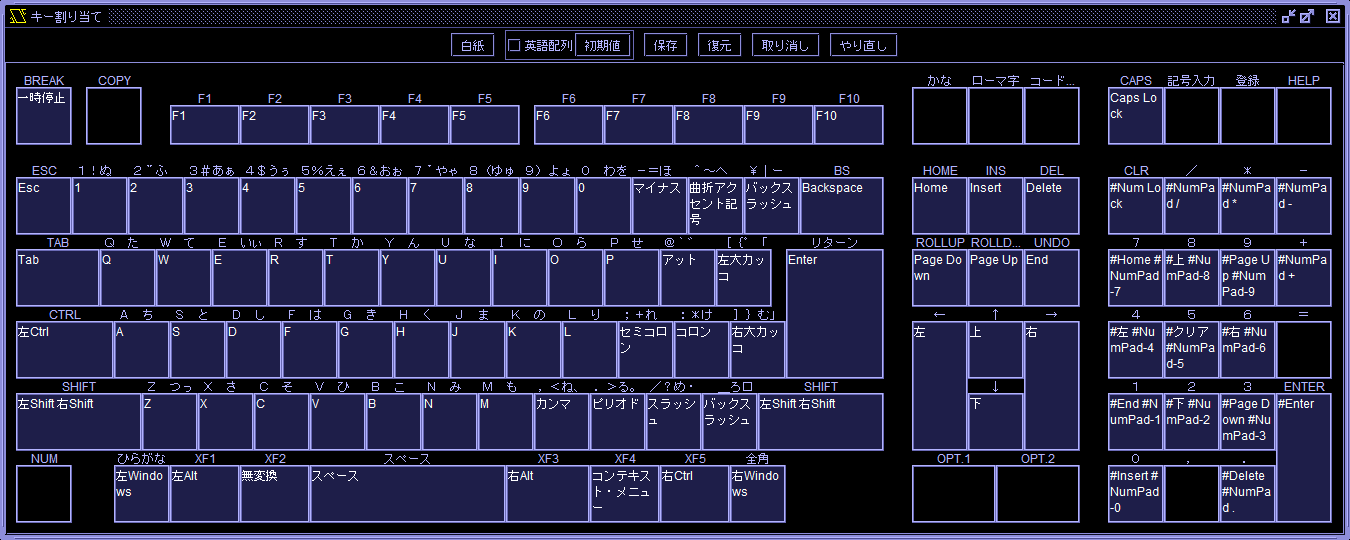
The Key assignments window allows you to set the correspondence between the keys on the X68000 and the keys on the host machine. キー割り当てウインドウで X68000 のキーとホストマシンのキーの対応を設定できます。
31.1. Input area 入力エリア
The Key assignments window has input areas arranged in the shape of a standard X68000 keyboard. Click on the input area of the X68000 key you want to assign, and then press the key on the host machine you want to assign. キー割り当てウインドウには入力エリアが X68000 の標準キーボードの形に並んでいます。 割り当てたい X68000 のキーの入力エリアをクリックしてから、割り当てたいホストマシンのキーを押してください。
You can assign up to three keys of the host machine's key to one key on the X68000. Pressing an unassigned key will add a key. Pressing the fourth key will unassign the first key and reduce the number of keys to three. Pressing a key that has already been assigned to a key will unlock the other key and reduce the number of keys to one. X68000 の 1 個のキーにホストマシンのキーのキーを 3 個まで割り当てられます。 割り当てられていないキーを押すとキーが追加されます。4 個目を押すと 1 個目が解除されて 3 個になります。 既に割り当てられているキーを押すと他のキーが解除されて 1 個になります。
Pressing the Esc key on the host machine other than the ESC key on the X68000 will cancel all assignments for that key and set it to 0. It is not possible to assign the Esc key to any key other than the ESC key. Also, the ESC key cannot be unassigned. X68000 の ESC キー以外でホストマシンの Esc キーを押すとそのキーの割り当てがすべて解除されて 0 個になります。ESC キー以外に Esc キーを割り当てることはできません。 また、ESC キーの割り当てを解除することはできません。
Pressing the Tab key on the host machine other than the TAB key on the X68000 will shift the focus to the next key. The Tab key cannot be assigned to any key other than the TAB key. X68000 の TAB キー以外でホストマシンの Tab キーを押すとフォーカスが次のキーに移ります。TAB キー以外に Tab キーを割り当てることはできません。
31.2. Blank button 白紙ボタン
Unassigns all keys. すべてのキーの割り当てを解除します。
31.3. US layout checkbox 英語配列チェックボックス
Selects whether or not to use the US layout when resetting to the initial value with the Default button. 初期値ボタンで初期値に戻すとき英語配列にするかどうか選択します。
31.4. Default button 初期値ボタン
Resets all key assignments to their default values. The default values are different for Windows, macOS, and Linux. すべてのキーの割り当てを初期値に戻します。Windows と macOS と Linux で初期値が異なります。
31.5. Save button 保存ボタン
Saves key assignments to a file in CSV format. Since XEiJ saves key assignments in a configuration file, when you initialize XEiJ settings, the key assignments are also initialized together. By saving key assignments to a file, you can restore key assignments after initializing XEiJ settings. キー割り当てを CSV 形式でファイルに保存します。XEiJ ではキー割り当てを設定ファイルに保存しているので、XEiJ の設定を初期化するとキー割り当ても一緒に初期化されてしまいます。 キー割り当てをファイルに保存しておくことで、XEiJ の設定を初期化した後にキー割り当てを復元できます。
31.6. Restore button 復元ボタン
Restores key assignments saved in a file in CSV format. CSV 形式でファイルに保存されたキー割り当てを復元します。
31.7. Undo button 取り消しボタン
Undo changes to key assignments. If a key assigned to another key is pressed by mistake when changing a key assignment, the two keys will be in the wrong state, but they can be undone together. Operations of the blank button, initial value button, and restore button can also be undone. You can undo up to 1000 previous changes until you exit XEiJ. To undo a key assignment change after exiting XEiJ, extract the keymap= line from the XEiJ.ini.bak file, write it to a file named keymap.txt, and restore it. キー割り当ての変更を取り消します。 キー割り当てを変更するとき他のキーに割り当てられているキーを間違って押してしまうと、2 つのキーが間違った状態になってしまいますが、まとめて取り消せます。 白紙ボタン、初期値ボタン、復元ボタンの操作も取り消せます。XEiJ を終了するまで、1000 回前の変更まで取り消せます。XEiJ を終了した後にキー割り当ての変更を取り消すには、XEiJ.ini.bak ファイルから keymap= の行を取り出して keymap.txt というファイルに書き込み、それを復元してください。
31.8. Redo Button やり直しボタン
Redo the undone operation. 取り消した操作をやり直します。
31.9. F11 and F12 keys F11 キーと F12 キー
The F11 and F12 keys can only be entered with the keys assigned in the key assignments window when the no function is selected in the F11/F12 and button function assignments window. F11 キーと F12 キーはF11/F12 およびボタン機能割り当てウインドウで機能なしを選択したときだけキー割り当てウインドウで割り当てたキーを入力できます。
32. Logical space monitor 論理空間モニタ
Logical space monitor shows physical address assigned to logical address. 論理アドレスに割り当てられている物理アドレスを表示します。
33. MEGA DRIVE 3 button pad メガドラ 3 ボタンパッド
You can connect MEGA DRIVE 3 button pads to joystick ports. Joystick driver that supports the Chelnov adapter is required to use them. ジョイスティックポートにメガドラ 3 ボタンパッドを接続できます。メガドラパッド変換アダプタに対応しているジョイスティックドライバが必要です。
Settings of MEGA DRIVE 3 button pads are stored in the parameter megadrive3buttonN. メガドラ 3 ボタンパッドの設定はパラメータ megadrive3buttonN に保存されます。
34. MEGA DRIVE 6 button pad メガドラ 6 ボタンパッド
You can connect MEGA DRIVE 6 button pads to joystick ports. Joystick driver that supports the Chelnov adapter is required to use them. ジョイスティックポートにメガドラ 6 ボタンパッドを接続できます。メガドラパッド変換アダプタに対応しているジョイスティックドライバが必要です。
Settings of MEGA DRIVE 6 button pads are stored in the parameter megadrive6buttonN. メガドラ 6 ボタンパッドの設定はパラメータ megadrive6buttonN に保存されます。
35. Memory dump list メモリダンプリスト
Contents of memory are shown. メモリの内容を表示します。
36. Mercury-Unit V4 (MK-MU1) Mercury-Unit V4 (MK-MU1)
The Mercury-Unit V4 (MK-MU1) is available. It supports PCM output and 768x512 dot 256-color mode. Mercury-Unit V4 (MK-MU1) が使えます。PCM 出力と 768x512 ドット 256 色モードに対応しています。
Enabling the Mercury-Unit V4 (MK-MU1) checkbox in the sound menu activates the Mercury-Unit V4 (MK-MU1). This setting is saved in the parameter mercury. 音声メニューの Mercury-Unit V4 (MK-MU1) チェックボックスを ON にすると、Mercury-Unit V4 (MK-MU1) が有効になります。 この設定はパラメータ mercuryに保存されます。
Disabling the MU4 output checkbox in the sound menu mutes only the Mercury-Unit output. This setting is saved in the parameter mercuryoe. 音声メニューの MU4 出力チェックボックスを OFF にすることで、Mercury-Unit の出力だけミュートできます。 この設定はパラメータ mercuryoeに保存されます。
Since it's V4, some software requires running MKMU.R beforehand when performing PCM output, just like on the actual hardware. V4 ですので、PCM 出力を行うとき実機と同様にMKMU.Rを実行しておく必要があるソフトウェアがあります。
The 768x512 dot 256-color mode is configured using m256.x. You can test it with m256test.x. 768x512 ドット 256 色モードはm256.xで設定します。 m256test.xでテストできます。
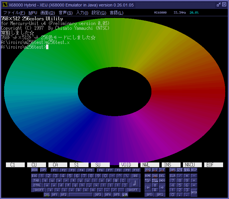
The 768x512 dot 256-color mode of the Mercury-Unit V4 does not function on the first model. This is because only the first model has negative logic for the HSYNC and VSYNC signals on the expansion slot. Mercury-Unit V4 の 768x512 ドット 256 色モードは初代だけ動作しません。 これは初代だけ拡張スロットの HSYNC と VSYNC が負論理であるためです。
37. Model 機種
The MPU type and operating frequency, IPLROM version, built-in hard disk interface type, etc. are automatically set according to the model selected in the change the model and reset menu or parameter model. 機種を変更してリセットメニューまたはパラメータ modelで選択された機種に応じて、MPU の種類と動作周波数、IPLROM のバージョン、内蔵ハードディスクインターフェイスの種類などが自動的に設定されます。
37.1. X68000 / X68000 ACE / X68000 EXPERT
The MPU type is MC68000 and the operating frequency is 10 MHz. The IPLROM version is 1.0. Internal hard disk interface type is SASI. MPU の種類は MC68000、動作周波数は 10MHz です。IPLROM のバージョンは 1.0 です。 内蔵ハードディスクインターフェイスの種類は SASI です。
37.2. X68000 PRO
PRO has one more DMAC wait cycle than EXPERT, so DMA transfers are slightly slower. PRO は EXPERT よりも DMAC のウェイトサイクルが 1 個多いので、DMA 転送が少し遅くなります。
37.3. X68000 SUPER
The MPU type is MC68000 and the operating frequency is 10 MHz. The IPLROM version is 1.0. Internal hard disk interface type is SCSI. MPU の種類は MC68000、動作周波数は 10MHz です。IPLROM のバージョンは 1.0 です。 内蔵ハードディスクインターフェイスの種類は SCSI です。
37.4. X68000 XVI
The MPU type is MC68000 and the operating frequency is 16.7 MHz. The IPLROM version is 1.1. Internal hard disk interface type is SCSI. MPU の種類は MC68000、動作周波数は 16.7MHz です。IPLROM のバージョンは 1.1 です。 内蔵ハードディスクインターフェイスの種類は SCSI です。
37.5. Xellent30
Xellent30 on X68000 XVI. The MC68EC030 operates at twice the frequency of the MC68000. You can switch between MC68EC030 and MC68000 without resetting. X68000 XVI に Xellent30 を載せます。MC68EC030 は MC68000 の 2 倍の周波数で動作します。MC68EC030 と MC68000 をリセットせずに切り替えることができます。
37.6. X68000 Compact
MPU の種類は MC68000、動作周波数は 16.7MHz です。IPLROM のバージョンは 1.2 です。 内蔵ハードディスクインターフェイスの種類は SCSI です。 MPU の種類は MC68000、動作周波数は 16.7MHz です。IPLROM のバージョンは 1.2 です。 内蔵ハードディスクインターフェイスの種類は SCSI です。
37.7. X68000 Hybrid
The X68000 Hybrid is XEiJ's default model, a fictional X68000 Compact with an X68030 IPLROM. The MPU type is MC68000 and the operating frequency is 33.3 MHz. The version of IPLROM is IPLROM 1.6. The type of internal hard disk interface is SCSI. X68000 Hybrid は XEiJ のデフォルトの機種で、X68000 Compact に X68030 の IPLROM を載せた架空の機種です。MPU の種類は MC68000、動作周波数は 33.3MHz です。IPLROM のバージョンはIPLROM 1.6です。 内蔵ハードディスクインターフェイスの種類は SCSI です。
37.8. X68030 / 030Compact
The MPU type is MC68EC030 and the operating frequency is 25 MHz. The version of IPLROM is IPLROM 1.3. The type of internal hard disk interface is SCSI. MPU の種類は MC68EC030、動作周波数は 25MHz です。IPLROM のバージョンは 1.3 です。 内蔵ハードディスクインターフェイスの種類は SCSI です。
37.9. 060turbo
060turbo on X68030. The MPU type is MC68060 and the operating frequency is 50 MHz. The version of IPLROM is IPLROM 1.6. The type of internal hard disk interface is SCSI. X68030 に 060turbo を載せます。MPU の種類は MC68060、動作周波数は 50MHz です。IPLROM のバージョンはIPLROM 1.6です。 内蔵ハードディスクインターフェイスの種類は SCSI です。
37.10. 060turboPRO
060turboPRO is a fictional model of X68000 PRO with 060turbo. The MPU type is MC68060 and the operating frequency is 50 MHz. The version of IPLROM is IPLROM 1.6. The type of internal hard disk interface is SCSI. 060turboPRO は X68000 PRO に 060turbo を載せた架空の機種です。MPU の種類は MC68060、動作周波数は 50MHz です。IPLROM のバージョンはIPLROM 1.6です。 内蔵ハードディスクインターフェイスの種類は SASI です。
38. Mother board coprocessor マザーボードコプロセッサ
From a comparative view point between the mother board and daughter board, I call MC68882 on mother board of X68030 a mother board coprocessor. Mother board coprocessor is used when MC68EC030 performs floating point instructions. MC68060 on daughter board can access mother board coprocessor via CPU space. Presence and type of mother board coprocessor are displayed in the starting messages in 060turbo mode. ドーターボードにある MC68060 から見てマザーボードにある MC68882 をマザーボードコプロセッサと呼んでいます。X68030 (実機) で MC68EC030 が浮動小数点命令を実行するときに使用するコプロセッサに、060turbo (実機) と同様に MC68060 からアクセスできます。起動メッセージなどでマザーボードコプロセッサの有無と種類が表示されます。
39. Normal 2 button pad ノーマル 2 ボタンパッド
You can connect normal 2 button pads to joystick ports. It is a normal joy pad. No special joystick driver is required to use them. ジョイスティックポートにノーマル 2 ボタンパッドを接続できます。普通のジョイパッドです。特別なジョイスティックドライバは不要です。
Settings of normal 2 button pads are stored in the parameter normal2buttonN. ノーマル 2 ボタンパッドの設定はパラメータ normal2buttonN に保存されます。
40. Number of sprites スプライトの枚数
The number of sprites can be selected from 128, 256, 504, and 1016 in the modification menu. Changes will take effect after the reset. This setting is saved in the parameter numspr. 改造メニューでスプライトの枚数を 128、256、504、1016 から選べます。 変更はリセット後に反映されます。 この設定はパラメータ numsprに保存されます。
There are 1024 sprites numbered from 0 to 1023, but 8 sprites numbered from 256 to 263 are missing. In terms of the sprite scroll register addresses, $00EB0000 to $00EB1FFF, of which $00EB0800 to $00EB083F are in the range of missing numbers. Since there are control registers in the missing range, be careful not to write to them as if they were sprite scroll registers. スプライトの番号は 0 番から 1023 番までの 1024 個ですが、256 番から 263 番までの 8 個は欠番です。 スプライトスクロールレジスタのアドレスで言うと、$00EB0000~$00EB1FFF のうち $00EB0800~$00EB083F が欠番の範囲です。 欠番の範囲には制御レジスタがあるので、スプライトスクロールレジスタのつもりで書き込まないように注意してください。
41. OPM log OPM ログ
Writes to YM2151 registers during operation can be recorded with the elapsed time in units of 1 μ s and the performance can be replayed. 動作中の YM2151 のレジスタへの書き込みを 1 μ s 単位の経過時間とともに記録して演奏を再生できます。
You can check the emulation of YM2151 and the operation of the sound source driver. YM2151 のエミュレーションや音源ドライバの動作を確認できます。
42. Palette viewer window パレットビュアウインドウ
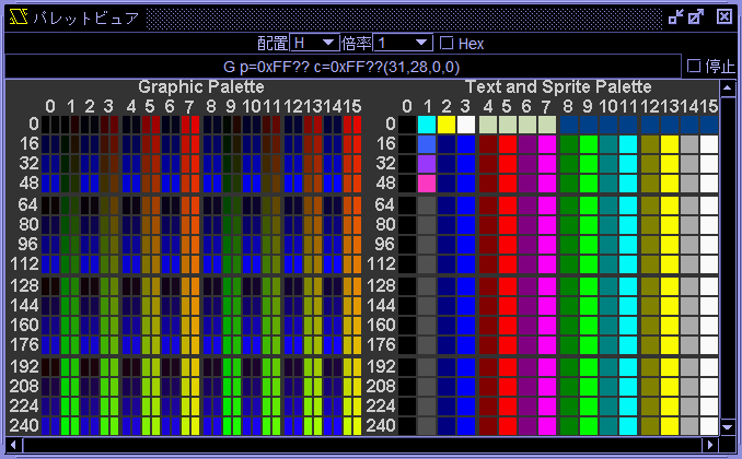
Clicking the palette viewer button in the display menu opens the palette viewer window. 画面メニューのパレットビュアボタンをクリックするとパレットビュアウインドウが開きます。
Arrgt drop-down list 配置ドロップダウンリスト
Use the Arrgt drop-down list to select the page from G, TS, H or V. G displays the graphic palette, TS displays the text and sprite palette, H displays both in horizontal alignment, and V displays both in vertical alignment. The default is H. This setting is saved in the parameter plvarrgt. 配置ドロップダウンリストを用いて表示するページを G、TS、H または V から選択します。G はグラフィックパレット、TS はテキストおよびスプライトパレット、H は両方を横並びで、V は両方を縦並びで表示します。 デフォルトは H です。 この設定はパラメータ plvarrgtに保存されます。
Scale drop-down list 倍率ドロップダウンリスト
Use the Scale drop-down list to select the display scale from 1/2 to 16. The default is 1. This setting is saved in the parameter plvscale. 倍率ドロップダウンリストを用いて表示倍率を 1/2~16 から選択します。 デフォルトは 1 です。 この設定はパラメータ plvscaleに保存されます。
Hex checkbox Hex チェックボックス
When the Hex checkbox is ON, the header numbers are displayed in hexadecimal. The default is OFF. This setting is saved in the parameter plvhex. Hex チェックボックスが ON のときヘッダの数字が 16 進数で表示されます。 デフォルトは OFF です。 この設定はパラメータ plvhexに保存されます。
Text field テキストフィールド
The text field displays the page, number, palette code, and color code of the palette pointed to by the mouse pointer. テキストフィールドにはマウスポインタが指しているパレットのページ、番号、パレットコードおよびカラーコードが表示されます。
Stop checkbox 停止チェックボックス
When the Stop checkbox is turned ON, the system copies the information at that point and transitions to the stopped state. In the stopped state, the system is decoupled from the X68000's operation, allowing you to observe the palette at the moment it was stopped. 停止チェックボックスを ON にするとその時点の情報を複製して停止状態に移行します。 停止状態では X68000 の動作と切り離され、停止した時点のパレットを観察できます。
Mouse operation マウスによる操作
Use the wheel to change the display scale. ホイールで表示倍率を変更できます。
Drag to change the display position. ドラッグで表示位置を変更できます。
Left-click stops updating the text field. Left-click again to resume. 左クリックでテキストフィールドの更新が停止します。 もう一度左クリックで再開します。
Right-click displays a pop-up menu. Selecting Copy as hexadecimal copies one line of palette data as a hexadecimal string to the clipboard. 右クリックでポップアップメニューが表示されます。16 進数でコピーを選択すると 1 行分のパレットのデータが 16 進数の文字列でクリップボードにコピーされます。
43. Paste貼り付け
Transfers the text on the host machine's clipboard to the input buffer of the X68000's CON device (ASK68K.SYS). ホストマシンのクリップボードにあるテキストを X68000 の CON デバイス (ASK68K.SYS) の入力バッファに転送します。
44. Paste pipe 貼り付けパイプ
When the paste and control pipe checkbox in the pipe settings menu is turned on, you can enter strings into XEiJ from other processes via the paste pipe. This setting is saved in the parameter pastepipe. The entered strings are written to the input buffer of the CON device (ASK68K.SYS). The name of the control pipe is \\.\pipe\XEiJPaste on Windows and /tmp/XEiJPaste on WSL (Ubuntu). パイプ設定メニューにある貼り付けおよび制御パイプチェックボックスが ON のとき、貼り付けパイプを介して他のプロセスから XEiJ へ文字列を入力できます。 この設定はパラメータ pastepipeに保存されます。 入力された文字列は CON デバイス (ASK68K.SYS) の入力バッファに書き込まれます。 制御パイプの名前は Windows のとき \\.\pipe\XEiJPaste、WSL (Ubuntu) のとき /tmp/XEiJPaste です。
You can select the character encoding for the pipe using the SJIS radio button and UTF-8 radio button in the pipe settings menu. The default is SJIS. The change takes effect immediately. This setting is saved in the parameter pipeencoding. パイプ設定メニューの SJIS ラジオボタンと UTF-8 ラジオボタンでパイプの文字コードを選択できます。 デフォルトは SJIS です。 変更は直ちに反映されます。 この設定はパラメータ pipeencodingに保存されます。
>echo memfree > \\.\pipe\XEiJPaste
45. PCM interpolation algorithm PCM 補間アルゴリズム
PCM interpolation algorithms for converting the ADPCM sampling frequency (3.9kHz-31.3kHz) to the internal sampling frequency (62.5kHz) are : ADPCM のサンプリング周波数 (3.9kHz-31.3kHz) を内部サンプリング周波数 (62.5kHz) に変換するための PCM 補間アルゴリズムは以下の通りです :
- Piecewise-constant interpolation…Repeat the same value. This method is simple and fast but it increases noise because the waveform becomes stepwise. 区分定数補間 … 同じ値を繰り返します。単純で高速ですが、波形が階段状になるのでノイズが増えます。
- Linear interpolation…Connect preceding data and succeeding data by a straight line and resample by output sampling frequency. 線形補間 … 前後のデータを直線で結んでから出力サンプリング周波数で再サンプリングします。
- Hermite interpolation…Connect preceding data and succeeding data by a curved line by using four data and resample by output sampling frequency. エルミート補間 …4 つのデータを用いて 2 つのデータを曲線で結んでから出力サンプリング周波数で再サンプリングします。
46. Physical space monitor 物理空間モニタ
Physical space monitor shows devices assigned to each physical address. 物理アドレスに割り当てられているデバイスを表示します。
47. Printer プリンタ
Data that you output to printer port are converted into image files by each page. Fonts of host machine are used. For example, you can print a text file by doing : プリンタポートに出力されたデータを 1 ページずつ画像に変換してイメージファイルに出力します。ホストマシンのフォントを使います。例えば、テキストファイルは以下のようにすれば“印刷”できます。
B:\>type xxx.txt > prn
You can get a hard copy of screen by COPY key. Control code of the printer is "SHARP CZ 48-pin". Use PRNDRV.SYS (SHARP CZ 24-pin), which is the default printer driver, in Human68k environment. In case of SX-WINDOW, choose printer "SHARP CZ 48-pin" and color conversion system "Error diffusion (Floyd Steinberg) method" to get a fine color print. また、COPY キーで画面のハードコピーをとることができます。制御コードは「SHARP CZ 48 ピン」です。Human68k のプリンタドライバは標準の PRNDRV.SYS (SHARP CZ 24 ピン) を使います。SX-WINDOW ではプリンタを標準の「SHARP CZ 24 ピン」から「SHARP CZ 48 ピン」に変更してデフォルトの色変換方式を「誤差分散 (Floyd Steinberg) 方式」にすると綺麗に“カラー印刷”できます。
48. Program flow visualizer プログラムフロービジュアライザ
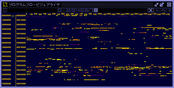
Program flow visualizer is a tool to visualize the branch log in real time. It shows where the program counter is walking in 4GB address space. By clicking a bright spot to disassemble code, you can tell what is done there. You will understand large structure of the program easily than tracing each instruction. プログラムフロービジュアライザは 分岐ログ をリアルタイムに可視化するツールです。プログラムカウンタが 4GB のアドレス空間のどこを巡回しているのかがひと目でわかり、クリックで逆アセンブルさせればそこで何をやっているのかもすぐにわかります。1 命令ずつトレースするよりもプログラムの大きな構造を把握しやすいと思います。
49. Raster break point ラスタブレークポイント
MPU stops at the beginning of the horizontal front porch of a specified fixed raster or the current IRQ raster. You can easily trace V-DISP, H-SYNC and CRTC IRQ interrupt routines because the MPU and the synchronous signal of CRTC stop simultaneously. That is difficult to do on real machines. 指定された固定ラスタまたは IRQ ラスタの水平フロントポーチの先頭で MPU を停止させます。MPU が止まると CRTC の同期信号も止まるので、実機では困難な V-DISP、H-SYNC、CRTC IRQ の割り込みルーチンのトレースが簡単にできます。
50. Register list レジスタリスト
Contents of program counter, status register, general registers and floating point registers are displayed on register window. Situation of the establishment of condition is shown too. プログラムカウンタ、ステータスレジスタ、汎用レジスタ、浮動小数点レジスタなどの内容を表示します。 条件の成立状況が表示されます。
Core control buttons are located. コア制御ボタンが配置されています。
51. Root pointer list ルートポインタリスト
You can choose a task that you want to stop in multi-task environment. マルチタスク環境で停止させるタスクを選択できます。
52. Rounded corner adjustment 角丸調整
The rounded corner adjustment prevents the corners of the screen from being cut off when switching to full-screen mode, provided the monitor has rounded corners and its aspect ratio is similar to that of the X68000 screen. This setting must be configured manually. Use the rounded corner ratio spinner in the display menu to specify the radius of the rounded corners as a percentage of the shorter side's length, then switch to full-screen mode. This setting is saved in the parameter roundedcornerratio. 角丸調整は、モニタの角が丸く、モニタと X68000 の画面の縦横比が近いとき、全画面表示にすると画面の角が欠ける問題を回避します。 この項目は手動で設定する必要があります。 画面メニューの角丸率スピナーで、短辺の長さに対する角丸の半径をパーセントで指定してから、全画面表示に切り替えてください。 この設定はパラメータ roundedcornerratioに保存されます。
The rounded corner shape is based on a Fermat cubic curve. 角丸の形状はフェルマー 3 次曲線を想定しています。
53. Row and column scroll 行スクロールと列スクロール
When the row and column scroll checkbox in the modification menu is turned on, background screen can be scrolled row by row and column by column. This setting is stored in the この設定はparameter sprrcscroll. 改造メニューの行スクロールと列スクロールチェックボックスが ON のとき、バックグラウンド画面を行毎および列毎にスクロールできます。 この設定はパラメータ sprrcscrollに保存されます。
64 words from $00EB2000 are BG0 row scroll registers, 64 words from $00EB2080 are BG1 row scroll registers, 64 words from $00EB2200 are BG0 column scroll registers, and 64 words from $00EB2280 are BG1 column scroll registers. $00EB2000 から 64 ワードが BG0 の行スクロールレジスタ、$00EB2080 から 64 ワードが BG1 の行スクロールレジスタ、$00EB2200 から 64 ワードが BG0 の列スクロールレジスタ、$00EB2280 から 64 ワードが BG1 の列スクロールレジスタです。
54. RS-232C and terminal window RS-232C とターミナルウインドウ
- RS-232C on X680x0 on XEiJ XEiJ 上の X680x0 の RS-232C
- Terminal on XEiJ XEiJ のターミナル
- Host machine serial port ホストマシンのシリアルポート
From the above three, you can choose two to connect. In the following, they are written as RS-232C, terminal, and serial port, respectively. 以上の 3 つから、2 つを選んで接続できるようにしました。 以下ではそれぞれ RS-232C、ターミナル、シリアルポートと書きます。
For example, small file exchanges can be made between the emulator and the actual machine. 例えば、エミュレータと実機の間で小規模なファイル交換ができます。
- Prepare a serial port on the host machine and connect it directly to the actual X680x0 machine with an RS-232C crossover cable. ホストマシンにシリアルポートを用意して RS-232C クロスケーブルで X680x0 実機と直結します。
- Connect the terminal to the serial port and send ZM.X (and RSDRV.SYS if necessary) to the actual X680x0 device with the terminal function. ターミナルとシリアルポートを接続し、ターミナルの機能で X680x0 実機に ZM.X(と必要ならば RSDRV.SYS) を送信します。
- Connecting the RS-232C and serial port creates a file exchange environment using ZM.X between the emulator and the actual device. RS-232C とシリアルポートを接続すると、エミュレータと実機の間で ZM.X によるファイル交換環境が出来上がります。
The sxmr.bas and TeraTerm written in file exchange with Windows are no longer needed and only XEiJ and ZM.X are needed for file exchange. RSDRV.SYS is on the Human68k 3.0 system disk and is used to set flow control to RTS. Windows とのファイル交換に書いた sxmr.bas と TeraTerm は不要になり、XEiJ と ZM.X だけでファイル交換ができます。RSDRV.SYS は Human68k 3.0 のシステムディスクに入っていてフロー制御を RTS にするとき使います。
Select RS-232C and terminal from the config menu to open the RS232C and terminal window. The RS-232C and terminal window is divided into connection, communication settings, transfer, and terminal. 「設定」メニューの「RS-232C とターミナル」を選択すると「RS232C とターミナル」ウインドウが開きます。 「RS232C とターミナル」ウインドウは「接続」、「通信設定」、「コマンド」、「ターミナル」に分かれています。
54.1. Connection 接続
In the "Connection" section of the "RS232C and terminal" window, you can select whether to connect to a terminal (Terminal), RS-232C (AUX), or serial port (COM3, etc.). This setting is stored in the parameter rs232cconnection. Pressing the "Refresh" button will re-search the serial port. 「RS232C とターミナル」ウインドウの「接続」では、ターミナル (Terminal)、RS-232C(AUX)、シリアルポート (COM3 など) のどれとどれを接続するか選択します。 この設定はパラメータ rs232cconnectionに保存されます。 「更新」ボタンを押すとシリアルポートが再検索されます。
When the port you want to connect to is not displayed after pressing the refresh button, enter the descriptor of the port you want to connect to in the additional port text field and press the refresh button. Typically, the descriptor is a string such as "COM[*]" on Windows or "/dev/tty[*]" on Linux and macOS. You can add ports that can be connected to with SerialPort.getCommPort(portDescriptor) but do not appear in the list of SerialPort.getCommPorts(). Be careful not to enter a descriptor for a port that does not exist or is already on the list. The contents of the additional port text field are stored in the parameter additionalport. 更新ボタンを押しても接続したいポートが表示されないとき、追加ポートテキストフィールドに接続したいポートのデスクリプタを入力して更新ボタンを押します。 通常、デスクリプタは Windows では「COM[*]」、Linux および macOS では「/dev/tty[*]」のような文字列です。SerialPort.getCommPort(portDescriptor) で接続できるが SerialPort.getCommPorts() のリストに出てこないポートを追加できます。 存在しないポートや既にリストにあるポートのデスクリプタを入力しないように注意してください。 追加ポートテキストフィールドの内容はパラメータ additionalportに保存されます。
54.2. Connect terminal and RS-232C ターミナルと RS-232C を接続する
When a terminal (Terminal) and RS-232C (AUX) are connected, the ROM debugger can be operated with the terminal as before. Also, when you want to copy a string of characters displayed on the screen by a command, you can easily copy it by using "CTTY AUX" to move the command prompt to the terminal and execute the command. ターミナル (Terminal) と RS-232C(AUX) を接続すると、従来通りターミナルで ROM デバッガを操作できます。 また、コマンドが画面に表示した文字列をコピーしたいとき、「CTTY AUX」でコマンドプロンプトをターミナルに移してコマンドを実行すると簡単にコピーできます。
54.3. Connect serial port and RS-232C シリアルポートと RS-232C を接続する
By connecting a serial port (e.g. COM3) and RS-232C (AUX), serial communication between X680x0 on XEiJ and a device outside the host machine is possible. You may be able to exchange files with the actual X680x0 machine and even play communication games. シリアルポート (COM3 など) と RS-232C(AUX) を接続すると、XEiJ 上の X680x0 とホストマシンの外にある機器の間でシリアル通信ができます。X680x0 実機とファイルのやり取りをしたり、通信対戦もできるかも知れません。
54.4. Connect serial port and terminal シリアルポートとターミナルを接続する
If you connect a serial port (COM3, etc.) to a terminal (Terminal), you can move the command prompt of the actual X680x0 device to the terminal. In the "Communication settings" section, match the settings with those of the actual device and enter "CTTY AUX" on the actual device. シリアルポート (COM3 など) とターミナル (Terminal) を接続すると、X680x0 実機のコマンドプロンプトをターミナルに移すことができます。 「通信設定」で実機と設定を合わせて実機で「CTTY AUX」と入力します。
54.5. Communication settings 通信設定
"Communication settings" in the "RS232C and terminal" window is used when a serial port (e.g. COM3) is connected to a terminal (Terminal). It selects baud rate, data bits, parity, stop bit, and flow control. These settings are stored in the parameter terminalsettings. 「RS232C とターミナル」ウインドウの「通信設定」は、シリアルポート (COM3 など) とターミナル (Terminal) を接続しているときに使います。 ボーレート、データビット、パリティ、ストップビット、フロー制御を選択します。 この設定はパラメータ terminalsettingsに保存されます。
54.6. Send file ファイル送信
The "Send file" button under "Command" in the "RS232C and terminal" window is used to transfer a small file from the host to the actual X680x0 device when the serial port (COM3, etc.) is connected to the terminal (Terminal). Type "CTTY AUX" on the actual device to move the command prompt of the actual device to the terminal, press the "Send file" button, select a file, and press the "Send" button. The selected file is converted into a self-restoring file named a.r that does not contain any control code, and is sent in the following order: string "copy aux a.r", new line, contents of a.r, string "a.r", new line. As long as COMMAND.X is running on the actual device, the process of converting a binary file into a file that does not contain control codes, sending it, and restoring it is done automatically. 「RS232C とターミナル」ウインドウの「コマンド」の「ファイル送信」ボタンは、シリアルポート (COM3 など) とターミナル (Terminal) を接続しているとき、ホストから X680x0 実機に小さいファイルを転送したいときに使います。 実機で「CTTY AUX」と入力して実機のコマンドプロンプトをターミナルに移し、「ファイル送信」ボタンを押してファイルを選択して、「送信」ボタンを押します。 選択されたファイルが、制御コードを含まない a.r という自己復元ファイルに変換され、文字列「copy aux a.r」、改行、a.r の内容、文字列「a.r」、改行の順に送信されます。 実機で COMMAND.X さえ動いていれば、バイナリファイルを制御コードを含まないファイルに変換して送信して復元する作業が自動で行われます。
This transfer function is a simple one that uses the COMMAND.X copy command. The file to be transferred must fit into the memory of the actual device, including the area needed for decompression. Once the transfer is started, it cannot be stopped. The transfer may not be stopped due to communication errors. If the decoder is corrupted, a white window may appear. If the file is corrupted, a CRC error will be displayed. If the transfer fails, check the flow control, lower the baud rate, and try again. Data bits must be 8 bits. この転送機能は COMMAND.X の copy コマンドを用いる簡易的なものです。 転送するファイルは解凍に必要な領域を含めて実機のメモリに収まらなければなりません。 転送を始めたら途中で止められません。 通信エラーで転送が止まらなくなることがあるかも知れません。 デコーダが破損したときは白窓が表示されるかも知れません。 ファイルが破損したときは CRC エラーが表示されます。 転送に失敗するときはフロー制御を確認してボーレートを下げてやり直してください。 データビットは 8 ビットに限ります。
54.7. Set clock 時計合わせ
When the date and time on a real X68000 machine are incorrect -- for example, due to a dead SRAM battery -- this button allows you to set the date and time using the DATE and TIME commands with a single click. SRAM の電池切れなどで X68000 実機の日時が合っていないとき、DATE コマンド TIME コマンドで日時を合わせる作業をボタン 1 つで済ませます。
54.8. Send ^C ^C 送信
At the terminal, press the Pause key or select "Send ^C" from the pop-up menu to send 0x03. ターミナルで、Pause キーを押すか、ポップアップメニューの「^C 送信」を選択すると、0x03 が送信されます。
55. Scanline effect 走査線エフェクト
In low-resolution mode, you can choose how to represent gaps between scanning lines. This is a feature designed to give the atmosphere of a CRT in a non-powerful execution environment. It is well known that two vertical dots on an LCD monitor cannot represent one vertical dot on a CRT. 低解像度モードのとき走査線の隙間を表現する方法を選択できます。 これは非力な実行環境でブラウン管の雰囲気を出そうとして作られた機能です。 液晶モニタの縦 2 ドットでブラウン管の縦 1 ドットを表現できないことは百も承知です。
If the vertical magnification of the screen is not an integer multiple and not large enough, the scanline effect will not look good. Use Fixed scale to set the screen's vertical magnification to an integer multiple. 画面の縦方向の倍率が整数倍でなくかつ十分に大きくないとき、走査線エフェクトは綺麗に見えません。 固定倍率を用いて画面の縦方向の倍率を整数倍にしてください。
Off なし
Copies the displayed raster as is. 表示したラスタをそのままコピーします。
Weak 弱
Copies the displayed raster with brightness multiplied by 7/8. 表示したラスタを明るさを 7/8 倍してコピーします。
Medium 中
Copies the displayed raster with brightness multiplied by 3/4. 表示したラスタを明るさを 3/4 倍してコピーします。
Strong 強
Copies the displayed raster with brightness multiplied by 1/2. 表示したラスタを明るさを 1/2 倍してコピーします。
Black 黒
Draw a black line. 黒線を描きます。
56. Screen mode test window 表示モードテストウィンドウ

Selecting screen mode test in the display menu opens the screen mode test window. The screen mode test window displays registers for the CRTC, video controller, and sprite controller. The upper frame of each item is the value written to the port, and the lower frame is the value for testing. Switching the radio button to the lower frame reflects the value for testing. The test values are not visible to the MPU. 画面メニューの表示モードテストを選択すると表示モードテストウィンドウが開きます。 表示モードテストウィンドウには、CRTC、ビデオコントローラ、スプライトコントローラのレジスタが表示されます。 各項目の上の枠はポートに書き込まれた値、下の枠はテスト用の値です。 ラジオボタンを下の枠に切り替えるとテスト用の値が反映されます。 テスト用の値は MPU からは見えません。
56.1. Pattern test パターンテスト

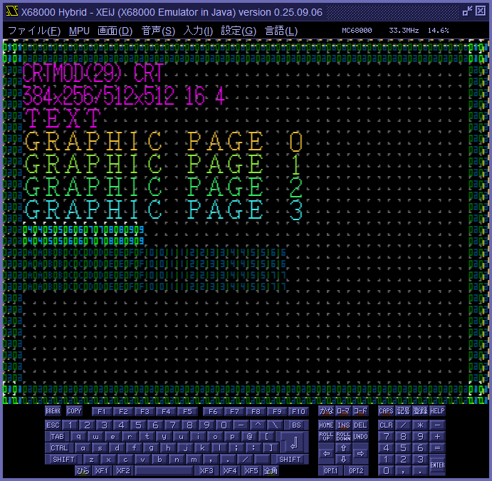
By replacing sprite patterns with patterns written in hexadecimal pattern numbers, the pattern numbers of displayed sprites and backgrounds become visible. The pattern numbers of foreground sprites appear bright, while those of background sprites and backgrounds appear dim. This allows you to play familiar shooting games with pattern numbers displayed. When the sprite number checkbox is ON, sprites display their sprite number instead of their pattern number. スプライトパターンを、パターン番号を 16 進数で書いたパターンで置き換えることで、表示されているスプライトとバックグラウンドのパターン番号を可視化します。 手前のスプライトのパターン番号は明るく、奥のスプライトとバックグラウンドのパターン番号は暗く表示されるようになっており、遊び慣れたシューティングゲームなどはパターン番号を表示した状態で動かせます。 スプライト番号チェックボックスが ON のとき、スプライトにはパターン番号ではなくスプライト番号が表示されます。
57. Screen rotation 画面の回転
You can choose a screen rotation from no rotation (landscape), 90-degree rotation (portrait), 180-degree rotation, or 270-degree rotation in the rotation menu in the display menu. This setting is saved in the parameter rotation. 画面メニューにある回転メニューで画面の回転を回転なし (横画面)、90 度回転 (縦画面)、180 度回転、270 度回転から選べます。 この設定はパラメータ rotationに保存されます。
58. Seamless mouse mode シームレスマウスモード
The seamless mouse mode is default mouse mode of XEiJ. Mouse cursor of host machine turns into mouse cursor of X68000 and acts as mouse cursor of IOCS or SX-WINDOW when it moves over the screen of X68000. You can operate software of X68000 that uses a mouse with the feeling of applications of host machine without monopolizing mouse cursor of host machine. Jong helps to understand effect of the seamless mouse mode. You can also easily operate DSHELL that is a special browser for the Dennou Club. In the case of SX-WINDOW (FSX.X version 3.10), you can also use the actual screen mode under the seamless mouse mode if edge acceleration is enabled. シームレスマウスモードは XEiJ のデフォルトのマウスモードです。 ホストマシンのマウスカーソルが X68000 の画面に差し掛かった瞬間に X68000 のマウスカーソルに化け、X68000 の画面から出た瞬間にホストマシンのマウスカーソルに戻ります。 ホストマシンのマウスカーソルは X68000 のマウスカーソルに化けている間だけ X68000 の IOCS または SX-WINDOW のマウスカーソルとして振る舞います。X68000 用のマウスを使うソフトウェアをマウスカーソルを占有せずにホストマシンのアプリケーションに近い感覚で操作することができます。 シームレスマウスモードの効果はじょんぐを見ていただくとわかりやすいと思います。 電脳倶楽部の DSHELL もらくらく操作できます。SX-WINDOW(FSX.X version 3.10) の場合は縁部加速を ON にすると実画面モードもシームレスのまま操作できます。
Switching between seamless and exclusive mouse modes is assigned to the F12 key and mouse wheel by default. This assignment can be changed in the F11/F12 and button function assignments window. シームレスマウスモードとエクスクルーシブマウスモードの切り替えはデフォルトで F12 キーとマウスホイールに割り当てられています。 この割り当てはF11/F12 およびボタン機能割り当てウインドウで変更できます。
58.1. How to make the seamless mouse mode シームレスマウスモードの作り方
To stick mouse cursor of X68000 on mouse cursor of host machine, perform reverse accelerating calculation by relative position of them. Make transparent mouse cursor of host machine while it moves over the screen of X68000 and mouse cursor of X68000 is displayed. If you know current position of mouse cursor and the formula of reverse accelerating calculation, you will be able to perform the same method on other emulators. X68000 のマウスカーソルとホストマシンのマウスカーソルの相対位置を元に逆アクセラレーション計算を行ってマウスデータを作り、X68000 のマウスカーソルをホストマシンのマウスカーソルの真下に貼り付けます。 さらに、X68000 のマウスカーソルが表示されていてホストマシンのマウスカーソルが X68000 の画面の上にある間だけホストマシンのマウスカーソルを透明にします。 これでホストマシンのマウスカーソルが X68000 の画面の上にある間だけ X68000 のマウスカーソルに化けたように見えます。 マウスカーソルの座標とアクセラレーションの計算式が分かれば IOCS でなくても、あるいは X68000 のエミュレータでなくても、同じことができると思います。
58.2. How to click by the multi-touch trackpad on Macbook Macbook のマルチタッチトラックパッドでクリックする方法
Left click…Apple menu→System Preferences→Trackpad→Enable "Tap to click". Tap with one finger. 左クリック…「リンゴ」→「システム環境設定」→「トラックパッド」の「タップでクリック」を ON にしておいて、1 本指でタップします。
Right click…Apple menu→System Preferences→Trackpad→Enable "Secondary click" and choose "Click or tap with two fingers". Tap with two fingers. 右クリック…「リンゴ」→「システム環境設定」→「トラックパッド」の「副ボタンのクリック」を ON にして「2 本指でクリックまたはタップ」を選択しておいて、2 本指でタップします。
59. Shiromadokun emulator 白窓君エミュレータ
Emulates TNB Seisakusho's LCD unit Shiromadokun. TNB 製作所さんの LCD ユニット「白窓君」をエミュレートします。
You can select Japanese specification or European specification in the joystick port settings window or with the parameter shiromadokunN. ジョイスティックポート設定ウインドウまたはパラメータshiromadokunNで日本仕様と欧州仕様を選択できます。
60. Sound interpolation algorithm 音声補間アルゴリズム
Sound interpolation algorithms for converting the internal sampling frequency (62.5kHz) to the output sampling frequency (48kHz) are : 内部サンプリング周波数 (62.5kHz) を出力サンプリング周波数 (48kHz) に変換するための音声補間アルゴリズムは以下の通りです :
- Thinning…Thin data. 間引き … データを間引きます。
- Linear interpolation…Perform linear interpolation and resample by output sampling frequency. 線形補間 … 線形補間してから出力サンプリング周波数で再サンプリングします。
- Piecewise-constant-area interpolation…Perform piecewise-constant interpolation, subdivide by output sampling interval and output the arithmetic mean of each fragment. 区分定数面積補間 … 区分定数補間してから出力サンプリング間隔で刻み、各断片の変位の算術平均を出力します。
- Linear-area interpolation…Perform linear interpolation, subdivide by output sampling interval and output the arithmetic mean of each fragment. 線形面積補間 … 線形補間してから出力サンプリング間隔で刻み、各断片の変位の算術平均を出力します。
61. Sound monitor 音声モニタ
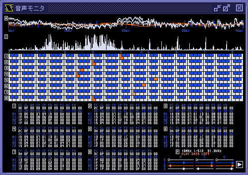
Waveforms, frequency distribution (spectrum analyzer), keyboards, tone data and ADPCM status are shown in the sound monitor of XEiJ. XEiJ の音声モニタには、波形、周波数分布 (スペクトラムアナライザ)、鍵盤、音色データおよび ADPCM の状態が表示されます。
Waveforms are waveforms before mixing OPM and ADPCM. You can zoom the graph in the direction of time axis by left-click or right-click. And you can zoom the graph in the direction of amplitude axis by Shift-left click or Shift-right click. Click the button in the bottom right corner to stop the graph before zooming a particular place. 波形は OPM と ADPCM の合成前の波形です。左クリックまたは右クリックで時間方向を拡大縮小、Shift キーを押しながら左クリックまたは右クリックで振幅方向を拡大縮小できます。波形の狙ったところを拡大縮小させたいときは右下のボタンで更新を停止させてから行います。
Frequency axis of the spectrum analyzer (FFT analyzer) are divided into five ranges to achieve both high resolution in lower range and high speed in upper range. Frequency axis is adjusted to the keyboard below instead of writing numerals. Emission lines of simple tones appear just above the center of corresponding key regardless of its color. スペクトラムアナライザ (FFT アナライザ) は低音域の分解能と高音域の反応速度を両立させるために周波数の範囲を 5 分割しています。また、どこが何 Hz か数字で書く代わりに周波数を下の鍵盤に合わせてあり、単純な音色ならば白鍵でも黒鍵でも鍵の中央の真上に輝線が現れます。
The keyboard shows which key is pressed. The nearest key to the frequency that consists of KC (KEY CODE) and KF (KEY FRACTION) in equal temperament reacts. 鍵盤はキーオンとリリースの様子を示しています。平均律で KC (KEY CODE) と KF (KEY FRACTION) を合わせた周波数に近い鍵が反応します。
The tone data are transformed contents of YM2151 registers in the format of MML tone definition data. It may be easier to read than raw data of registers. Displayed tone data do not always express the played sound because there are items that can not be perfectly recovered by only contents of YM2151 registers of a certain moment in MML tone definition data. 音色データは YM2151 のレジスタの内容を MML の音色定義データのフォーマットに変換したものです。レジスタの内容をそのまま表示するよりも読みやすいかも知れません。MML の音色定義データにはある瞬間の YM2151 のレジスタの内容だけでは復元できない項目もあるので、表示されたデータをそのまま用いても同じ音が出るとは限りません。
In the ADPCM status section, source oscillator frequency (4MHz | 8MHz | 16MHz), frequency division ratio (1/1024 | 1/768 | 1/512), sampling frequency (3.9kHz | 5.2kHz | 7.8kHz | 10.4kHz | 15.6kHz | 20.8kHz | 31.3kHz), playing (PLAY), data exists (DATA), left output (LEFT) and right output (RIGHT) are displayed. ADPCM の状態は、原発振周波数 (4MHz | 8MHz | 16MHz)、分周比 (1/1024 | 1/768 | 1/512)、サンプリング周波数 (3.9kHz | 5.2kHz | 7.8kHz | 10.4kHz | 15.6kHz | 20.8kHz | 31.3kHz)、再生中 (PLAY)、データあり (DATA)、左側出力 (LEFT)、右側出力 (RIGHT) が表示されます。
62. Source oscillator frequency 原発振周波数
The source oscillator frequency is the source of the sampling frequency of the ADPCM sound source. In case of an unmodified X68000, you can choose the source oscillator frequency from 8MHz and 4MHz. And you can choose the frequency division ratio from 1/1024, 1/768 and 1/512. Therefore, available sampling frequencies are 3.9kHz, 5.2kHz, 7.8kHz, 10.4kHz and 15.6kHz. ここで言う原発振周波数とは ADPCM 音源のサンプリング周波数の元となるオシレータ (水晶振動子) の発振周波数のことです。X68000 の ADPCM 音源は原発振周波数を 8MHz と 4MHz から、分周比を 1/1024、1/768、1/512 からそれぞれ選択できるので、サンプリング周波数は 3.9kHz、5.2kHz、7.8kHz、10.4kHz、15.6kHz の 5 種類となっています。
Method to replace the 4MHz oscillator with the 16MHz oscillator was published by Taki Yasushi in the article "project to improve sound quality of built-in ADPCM" in the fourth edition of "low-tech workshop" in the August 1994 issue of "Oh!X" magazine. Like the article, you can change the source oscillator frequency of XEiJ to 16MHz. The sampling frequencies after modification are 7.8kHz, 10.4kHz, 15.6kHz, 20.8kHz and 31.3kHz. PCM data will be reproduced in sampling frequency 31.3kHz by keeping PCM8A.X with switch "-M1 -F2". Oh!X 1994 年 8 月号の「ローテク工作実験室 第 4 回 内蔵 AD PCM 高音質化計画」(瀧康史さん) で 4MHz のオシレータを 16MHz のものに換装する方法が紹介されており、XEiJ はこの方法で ADPCM 音源を改造できます。改造後のサンプリング周波数は 7.8kHz、10.4kHz、15.6kHz、20.8kHz、31.3kHz の 5 種類になり、PCM8A.X に -M1 -F2 というスイッチを指定して常駐させることで PCM データがサンプリング周波数 31.3kHz で再生されるようになります。
You can confirm current source oscillator frequency, frequency division ratio and sampling frequency by the sound monitor. 現在の原発振周波数、分周比およびサンプリング周波数は 音声モニタ で確認することができます。
| frequency division ratio 分周比 | ||||
|---|---|---|---|---|
| 1/1024 | 1/768 | 1/512 | ||
| source oscillator frequency 原発振周波数 | 4MHz | 3.9kHz | 5.2kHz | 7.8kHz |
| 8MHz | 7.8kHz | 10.4kHz | 15.6kHz | |
| 16MHz | 15.6kHz | 20.8kHz | 31.3kHz | |
63. BG1 displayed in 512x512 512x512 で BG1 を表示
If the BG1 displayed in 512x512 checkbox in the modification menu is checked and reset, the BG1 can be displayed in 512x512. 改造メニューの512x512 で BG1 を表示チェックボックスを ON にしてリセットすると、512x512 で BG1 を表示できるようになります。
This setting is stored in the parameter spr512bg1. この設定はパラメータ spr512bg1に保存されます。
Remove the limitation that only one background plane can be displayed in 512x512. It is possible to display two planes of background in 512x512 as well as in 256x256. 512x512 のときはバックグラウンドを 1 面しか表示できないという制限を解除します。256x256 のときと同様に 512x512 のときもバックグラウンドを 2 面表示できるようになります。
64. Sprites displayed in 768x512 768x512 でスプライトを表示
If the sprites displayed in 768x512 checkbox in the modification menu is checked and reset, the sprite screen can be displayed in 768x512. 改造メニューの768x512 でスプライトを表示チェックボックスを ON にしてリセットすると、768x512 でスプライト画面を表示できるようになります。
This setting is stored in the parameter spr768x512. この設定はパラメータ spr768x512に保存されます。
The restriction that the sprite screen cannot be displayed when the lower 5 bits of R20 of CRTC are %1xx1x is removed. CRTC の R20 の下位 5 ビットが %1xx1x のときスプライト画面を表示できないという制限を解除します。
Bits 4, 1, and 0 of R20 of CRTC select the dot clock (oscillator and frequency divider ratio). For %1xx1x, the dot clock is 25 MHz or higher, which corresponds to 768x512, 1024x424, 1024x848, and 640x480 in CRTMOD 16 to 19 in standard screen mode. CRTC の R20 のビット 4,1,0 はドットクロック (オシレータと分周比) を選択します。%1xx1x はドットクロックが 25MHz 以上で、標準の画面モードでは CRTMOD 16~19 の 768x512、1024x424、1024x848、640x480 が該当します。
This limitation is so strong that even if one wanted to display a sprite screen at 768x512, just accessing the sprite area, pattern area, or text area would cause a bus error and there is no way to solve the problem. この制限は強く、768x512 でスプライト画面を表示したくてもスプライトエリア、パターンエリア、テキストエリアにアクセスしただけでバスエラーが発生してしまい、取り付く島もありません。
By removing this limitation, the sprite screen can be displayed even in 768x512. この制限を解除することで、768x512 でもスプライト画面を表示できるようになります。
65. Sprite pattern viewer window スプライトパターンビュアウインドウ
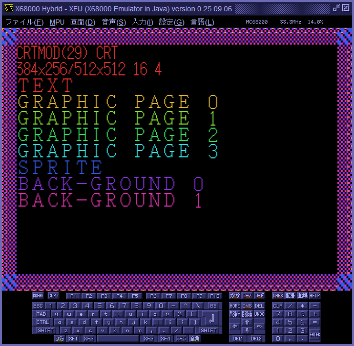
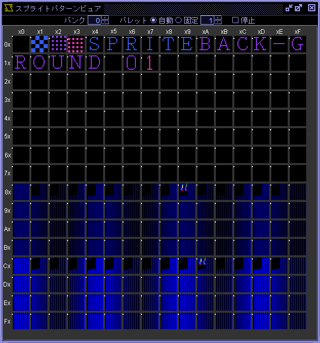
Clicking the sprite pattern viewer button in the display menu opens the sprite pattern viewer window. 画面メニューのスプライトパターンビュアボタンをクリックするとスプライトパターンビュアウインドウが開きます。
Bank drop-down list バンクドロップダウンリスト
Use the Bank drop-down list to select the pattern bank from 0 to 15, 0-3 to 12-15, or 0-15. The default is 0. Banks 1 to 15 are available when 4096 patterns are enabled. This setting is saved in the parameter spvbank. バンクドロップダウンリストを用いて表示するパターンのバンクを 0~15、0-3~12-15 または 0-15 から選択します。 デフォルトは 0 です。 バンク 1~15 は4096 個のパターンを有効にしたとき使用できます。 この設定はパラメータ spvbankに保存されます。
Size drop-down list サイズドロップダウンリスト
Use the Size drop-down list to select the pattern size from Auto, 8x8, or 16x16. The default is Auto, and the initial value is 16x16. When set to Auto, the information associated with the pattern is used when the pattern is displayed on the X68000 screen. Since the information is not updated until the pattern is displayed on the X68000 screen, the display may differ from expectations. The sprite pattern size is 16x16. The background pattern size is also 16x16 when the display screen size is 512x512. The background pattern size is 8x8 when the display screen size is 256x256. This setting is saved in the parameter spvsize. サイズドロップダウンリストを用いてパターンのサイズを自動、8x8 または 16x16 から選択します。 デフォルトは自動で初期値は 16x16 です。 自動のときはパターンが X68000 の画面に表示されたときにパターンに紐づけられた情報が使用されます。 パターンが X68000 の画面に表示されるまで情報が更新されないので、期待と異なる表示になることがあります。 スプライトのパターンのサイズは 16x16、表示画面サイズが 512x512 のときのバックグラウンドのパターンのサイズも 16x16、表示画面サイズが 256x256 のときのバックグラウンドパターンのサイズは 8x8 です。 この設定はパラメータ spvsizeに保存されます。
Block drop-down list ブロックドロップダウンリスト
Use the Block drop-down list to select the palette block from Auto, or 0 to 15. The default is Auto, and the initial value is 1. When set to Auto, the information associated with the pattern is used when the pattern is displayed on the X68000 screen. Since the information is not updated until the pattern is displayed on the X68000 screen, the display may differ from expectations. This setting is saved in the parameter spvblock. ブロックドロップダウンリストを用いてパレットブロックを自動または 0~15 から選択します。 デフォルトは自動で初期値は 1 です。 自動のときはパターンが X68000 の画面に表示されたときにパターンに紐づけられた情報が使用されます。 パターンが X68000 の画面に表示されるまで情報が更新されないので、期待と異なる表示になることがあります。 この設定はパラメータ spvblockに保存されます。
Flip drop-down list 反転ドロップダウンリスト
Use the Flip drop-down list to select the flip method from Auto, -, H, V or H&V. The default is Auto. When set to Auto, the information associated with the pattern is used when the pattern is displayed on the X68000 screen. Since the information is not updated until the pattern is displayed on the X68000 screen, the display may differ from expectations. A gray line and dots representing palette blocks are displayed on the left side of the pattern. When the pattern inverts, the line and dots invert together, allowing you to see the pattern's original orientation. This setting is saved in the parameter spvflip. 反転ドロップダウンリストを用いて反転を自動、なし、左右、上下または上下左右から選択します。 デフォルトは自動です。 自動のときはパターンが X68000 の画面に表示されたときにパターンに紐づけられた情報が使用されます。 パターンが X68000 の画面に表示されるまで情報が更新されないので、期待と異なる表示になることがあります。 パターンの左側に灰色の線とパレットブロックを表す点が表示されており、パターンが反転するとき線と点も一緒に反転することで、パターンの本来の向きが分かるようになっています。 この設定はパラメータ spvflipに保存されます。
Hex checkbox Hex チェックボックス
When the Hex checkbox is ON, the header numbers are displayed in hexadecimal. The default is OFF. This setting is saved in the parameter spvhex. Hex チェックボックスが ON のときヘッダの数字が 16 進数で表示されます。 デフォルトは OFF です。 この設定はパラメータ spvhexに保存されます。
Text field テキストフィールド
The text field displays the size, number, coordinates, palette code, and color code of the pattern pointed to by the mouse pointer. テキストフィールドにはマウスポインタが指しているパターンのサイズ、番号、座標、パレットコードおよびカラーコードが表示されます。
Scale drop-down list 倍率ドロップダウンリスト
Use the Scale drop-down list to select the display scale from 1 to 32. The default is 2. This setting is saved in the parameter spvscale. 倍率ドロップダウンリストを用いて表示倍率を 1~32 から選択します。 デフォルトは 2 です。 この設定はパラメータ spvscaleに保存されます。
Stop checkbox 停止チェックボックス
When the Stop checkbox is turned ON, the system copies the information at that point and transitions to the stopped state. In the stopped state, the system is decoupled from the X68000's operation, allowing you to observe the pattern at the moment it was stopped. 停止チェックボックスを ON にするとその時点の情報を複製して停止状態に移行します。 停止状態では X68000 の動作と切り離され、停止した時点のパターンを観察できます。
Mouse operation マウスによる操作
Use the wheel to change the display scale. ホイールで表示倍率を変更できます。
Drag to change the display position. ドラッグで表示位置を変更できます。
Left-click stops updating the text field. Left-click again to resume. 左クリックでテキストフィールドの更新が停止します。 もう一度左クリックで再開します。
Right-click displays a pop-up menu. Selecting Copy as hexadecimal copies the pattern data as a hexadecimal string to the clipboard. 右クリックでポップアップメニューが表示されます。16 進数でコピーを選択するとパターンのデータが 16 進数の文字列でクリップボードにコピーされます。
66. Stereoscopic viewing 立体視
It supports stereoscopic viewing using the STEREOSCOPIC connector on the back of the X68000. X68000 の背面にある STEREOSCOPIC コネクタを用いる立体視に対応しています。
The stereoscopic viewing method can be selected from naked-eye crossing method, naked-eye parallel method, side-by-side method, and top-and-bottom method. 立体視の方法を、裸眼交差法、裸眼平行法、サイドバイサイド、トップアンドボトムから選択できます。
67. Text screen copy テキスト画面コピー
Text screen copy is a function that reverses the character displayed as a bitmap image on the text screen to the character code and copies it to the clipboard. 8x8, 8x16, and 16x16 fonts in CGROM can be reverse-converted. Fonts loaded by "COPY XXX.FON @IOCS" etc. cannot be reverse-converted. Some characters are indistinguishable in principle, such as half-width space and full-width space. Light blue, yellow, bold, and reversal can be reverse-converted. Character attributes are not reflected in the result. Follows hardware scrolling. The coordinates of the character to be converted must be a multiple of 8x16. Characters that cannot be converted will be converted to "?". テキスト画面コピーはテキスト画面にビットマップ画像として表示されている文字を文字コードに逆変換してクリップボードにコピーする機能です。CGROM にある 8x8、8x16、16x16 のフォントを逆変換できます。 「COPY XXX.FON @IOCS」などで読み込まれたフォントは逆変換できません。 半角スペースと全角スペースのように原理上区別できない文字があります。 水色、黄色、太字、反転を逆変換できます。 文字属性は結果に反映されません。 ハードウェアスクロールに追従します。 変換する文字の座標は 8x16 の倍数に限ります。 変換できなかった文字は「?」になります。
Clicking text screen copy in the input menu or pressing Alt+Shift+C copies the text displayed in the set range to the clipboard. In the text screen copy setting menu, the range to be copied can be selected from four options: display area, C_WIDTH, entire VRAM, or last enclosed area. This setting is saved in the parameter textcopyarea. 入力メニューのテキスト画面コピーをクリックするか、Alt+Shift+C を押すと、設定された範囲に表示されているテキストがクリップボードにコピーされます。 テキスト画面コピー設定メニューで、コピーする範囲を表示領域、C_WIDTH、VRAM 全体、最後に囲んだ範囲の 4 つから選択できます。 この設定はパラメータ textcopyareaに保存されます。
When the enclose each time with mouse check box in the text screen copy setting menu is ON, pressing and dragging the left mouse button on the text screen will display a red frame, and releasing the button will copy the text inside the frame to the clipboard. This setting is saved in the parameter textcopy. テキスト画面コピー設定メニューのマウスで都度囲むチェックボックスが ON のとき、テキスト画面でマウスの左ボタンを押してドラッグすると赤い枠が表示され、ボタンを離すと枠の内側のテキストがクリップボードにコピーされます。 この設定はパラメータ textcopyに保存されます。
68. Triple precision floating point number 三倍精度浮動小数点数
XEiJ performs floating point arithmetic in higher precision than MC68882. Parameters and results can be read and written as 96-bit triple precision that is 16-bit longer than 80-bit extended precision. MC68882 stores an extended precision floating point number to memory with inserting 16-bit reserved area between exponent and mantissa. So an extended precision floating point number consumes a 96-bit area. XEiJ stores the least 16-bit of mantissa of a triple precision floating point number to the reserved area. Be careful when you use binary data that has non-zero reserved area in other environment. XEiJ は浮動小数点演算を MC68882 よりも高い精度で行い、その引数や結果を MC68882 の拡張精度 (80 ビット) よりも 16 ビット多い三倍精度 (96 ビット) で読み書きすることができます。MC68882 は拡張精度浮動小数点数を 16 ビットの予約領域を挟んで 96 ビットを消費する形でメモリに書き込みますが、XEiJ はその予約領域に三倍精度浮動小数点数の仮数部の末尾の 16 ビットを格納します。予約領域が $0000 になっていないのでバイナリデータを他所の環境で利用する場合は注意してください。
68.1. Example: Check the internal representation of the circular constant 例 : 円周率の内部表現を確認する
π = 3.141592653589793238462643383...
-l200000 20000d
  00200000      fmovecr.x       #$00,FP0
  00200004      fmove.x FP0,$00200010
  0020000C      _EXIT
In the case of extended precision 拡張精度のとき
0xc90fdaa22168c235/262 = 3.1415926535897932385128... (19 digit) (19 桁)
-g=200000
program terminated normally
-d200010 20001b
00200010  4000 0000 C90F DAA2 2168 C235                     @...ノ.レ「!hツ5
In the case of triple precision 三倍精度のとき
0xc90fdaa22168c234c4c6/278 = 3.141592653589793238462642109... (24 digit) (24 桁)
-g=200000
program terminated normally
-d200010 20001b
00200010  4000 C4C6 C90F DAA2 2168 C234                     @.トニノ.レ「!hツ4
69. CYBER STICK サイバースティック
A cyber stick can be connected to the joystick port. The analog mode can be operated with an XInput gamepad, and the digital mode can be operated with an XInput gamepad or keyboard. Cyberstick button assignments can be set in the joystick port settings window or with the parameters cyberstickanalogN and cyberstickdigitalN. ジョイスティックポートにサイバースティックを接続できます。 アナログモードは XInput 方式のゲームパッドで、また、デジタルモードは XInput 方式のゲームパッドまたはキーボードで操作できます。 サイバースティックのボタンの割り当てはジョイスティックポート設定ウインドウまたはパラメータcyberstickanalogNおよびcyberstickdigitalNで設定できます。
70. XInput support XInput 対応
When using Windows, the normal 2 button pad, the MEGA DRIVE 3 button pad, the MEGA DRIVE 6 button pad, and the cyber stick can be operated with an XInput gamepad. This functionality can be configured in the joystick port settings window or with the parameter xinput. Windows のとき、ノーマル 2 ボタンパッド、メガドラ 3 ボタンパッド、メガドラ 6 ボタンパッドおよびサイバースティックを XInput 方式のゲームパッドで操作できます。 この機能はジョイスティックポート設定ウインドウまたはパラメータ xinputで設定できます。
To use a DirectInput gamepad with XEiJ, you must install conversion software such as X360CE. We do not provide support for conversion software. XEiJ で DirectInput 方式のゲームパッドを使用するには、X360CE などの変換ソフトウェアをインストールする必要があります。 変換ソフトウェアに関するサポートは行っていません。
71. Z keyboard support Z キーボード対応
In a Windows 10 and Microsoft IME or Google Japanese Input environment, all keys on the X68000 Z keyboard can be entered, with some limitations, by remapping the special keys to the F13-F24 keys using Microsoft PowerToys Keyboard Manager. You can control the 7 LEDs on the X68000 Z keyboard. Windows 10 と Microsoft IME または Google 日本語入力の環境で、Microsoft PowerToys Keyboard Manager を用いて特殊キーを F13~F24 キーへ再マップすることで、いくつかの制約はありますが、X68000 Z のキーボードのすべてのキーを入力できます。X68000 Z のキーボードの 7 個の LED を制御できます。
This function can be selected in the Z keyboard menu or with the parameter zkeyboard. この機能はZ キーボードメニューまたはパラメータ zkeyboardで選択できます。
71.1. Input from the Z keyboard Z キーボードからの入力
Operating environment 動作環境
Input from the Z keyboard was adjusted using the X68000 Z EARLY ACCESS KIT keyboard and Windows 10 with Microsoft IME and Google Japanese Input. Z キーボードからの入力は X68000 Z EARLY ACCESS KIT のキーボードと Windows 10 と Microsoft IME および Google 日本語入力の環境で調整しました。
Restrictions 制約
Most keys can be operated in the same way as on the X68000, but there are still restrictions on the operation of some keys. In Microsoft IME or Google Japanese Input, it seems that AWT key events are not fired when the BREAK (Halfwidth/Fullwidth) key, CAPS (CapsLock i.e. alphanumeric) key and XF4 (Katakana/Hiragana) key are released. XEiJ uses AWT key events to know when keys are pressed or released, so the current method does not know when these keys are released. Therefore, the behavior of these three keys was changed as follows. 大部分のキーを X68000 と同じように操作できますが、一部のキーの動作に制約が残っています。Microsoft IME または Google 日本語入力の場合、BREAK(半角 / 全角) キーと CAPS(CapsLock すなわち英数字) キーと XF4(カタカナ / ひらがな) キーを離したときに AWT のキーイベントが発火しないようです。XEiJ はキーが押されたまたは離されたことを AWT のキーイベントで把握しているので、現在の方法ではこれらのキーがいつ離されたのか分かりません。 そこで、この 3 個のキーの動作を以下のように変更しました。
- The BREAK and CAPS keys are immediately released when pressed. BREAK キーと CAPS キーは押すと直ちに離されたことになります。
- The XF4 key remains pressed until another key is released. XF4 キーは押すと他のキーを離すまで押されたままになります。
Preparation 準備
The switch on the back of the Z keyboard is set to X68. The reason is that the CTRL and CAPS keys cannot be distinguished when set to WIN. The default key assignment is set to X68. Z キーボードの裏面のスイッチを X68 にします。 理由は、WIN になっていると CTRL キーと CAPS キーを区別できないからです。 キー割り当ての初期値は X68 に合わせてあります。
Install Microsoft PowerToys from the Microsoft Store and use Keyboard Manager to remap the following keys. Microsoft Store から Microsoft PowerToys をインストールして Keyboard Manager を使って以下のキーを再マップします。
| key on Z keyboardZ キーボードのキー | before remapping再マップ前 | after remapping再マップ後 |
|---|---|---|
| CTRL (Right)CTRL (右) | Ctrl (Right) | F11 |
| OPT.1 | F11 | F13 |
| XF2 | IME Non-Convert | F14 |
| XF3 | IME Convert | F15 |
| XF4 | VK 242 | F16 |
| CAPS | VK 240 | F17 |
| kanaかな | Print Screen | F18 |
| romajiローマ字 | Scroll Lock | F19 |
| hiraganaひらがな | Win (Left) | F20 |
| fullwidth全角 | Win (Right) | F21 |
| symbol input記号入力 | Volume Mute | F22 |
| registration登録 | Volume Down | F23 |
| HELP | Volume Up | F24 |
Remove F13 for direct input in the key settings of the properties of Google Japanese Input. If you do not remove it, you will not be able to input OPT.1 which is remapped to F13. Google 日本語入力のプロパティのキー設定で直接入力の F13 を削除します。 これを削除しないと F13 に再マップされている OPT.1 が入力できません。
| モード | 入力キー | コマンド |
| 直接入力 | F13 | IME を有効化 |
Key assignments キー割り当て
Select Connect in the Z keyboard menu to switch to key assignments for the Z keyboard. You can change key assignments for the Z keyboard in the Key assignments window. Key assignments for the Z keyboard are stored in the parameter zkeymap. Z キーボードメニューで接続を選択すると、Z キーボード用のキー割り当てに切り替わります。 キー割り当てウインドウで Z キーボード用のキー割り当てを変更できます。Z キーボード用のキー割り当てはパラメータ zkeymapに保存されます。
71.2. Control of LEDs on the Z keyboard Z キーボードの LED の制御
You can control the 7 LEDs on the keyboard of the X68000 Z. Thanks to yunk for disclosing the control method. X68000 Z のキーボードにある 7 個の LED を制御できます。 制御方法を公開してくださったyunk さんに感謝します。
Z keyboard LED control I/O port Z キーボード LED 制御 I/O ポート
The LEDs on the Z keyboard are over-specified for an X68000 keyboard, and each of the seven LEDs can be independently specified with 256 levels of brightness. It would be a waste not to take advantage of this, so XEiJ provides a programmable mode that allows direct specification of LED brightness via the Z keyboard LED control I/O port in addition to the normal mode. Z キーボードの LED は X68000 のキーボードとしてはオーバースペックで、7 個の LED に独立してそれぞれ 256 段階の輝度を指定できます。 これを活用しないのはもったいないので、XEiJ ではノーマルモードの他に Z キーボード LED 制御 I/O ポートを介して LED の輝度を直接指定できるプログラマブルモードを用意しました。
The Z keyboard LED control I/O ports are temporarily located at addresses $00E9F040 to $00E9F04F. Changing bit 0 of address $00E9F048 from 0 to 1 switches from normal mode to programmable mode. In programmable mode, setting the LED brightness to addresses $00E9F040 to $00E9F046 and writing 1 to bit 1 of address $00E9F048 will send the set brightness to the keyboard. The brightness is 0 for off and 255 for on. In normal mode, dark corresponds to 32, slightly dark to 64, slightly bright to 128, and bright to 255. Z キーボード LED 制御 I/O ポートはアドレス $00E9F040~$00E9F04F に仮に配置されています。 アドレス $00E9F048 の bit0 を 0 から 1 に変更するとノーマルモードからプログラマブルモードに切り替わります。 プログラマブルモードのときアドレス $00E9F040~$00E9F046 に LED の輝度を設定してアドレス $00E9F048 の bit1 に 1 を書き込むと設定された輝度がキーボードに送信されます。 輝度は 0 が消灯、255 が点灯です。 ノーマルモードの暗いは 32、やや暗いは 64、やや明るいは 128、明るいは 255 に相当します。
| I/O port address (temporary)I/O ポートアドレス (仮) | contents内容 | ||
|---|---|---|---|
| $00E9F040 | kanaかな | brightness of LED in programmable mode プログラマブルモードでの LED の輝度 | |
| $00E9F041 | romajiローマ字 | ||
| $00E9F042 | code inputコード入力 | ||
| $00E9F043 | CAPSCAPS | ||
| $00E9F044 | INSINS | ||
| $00E9F045 | hiraganaひらがな | ||
| $00E9F046 | fullwidth全角 | ||
| $00E9F047 | 0 | ||
| $00E9F048 | bit0 | 0=normal modeノーマルモード, 1=programmable modeプログラマブルモード | |
| bit1 | 1=send送信 | ||
| bit2-7 | 0 | ||
| $00E9F049-$00E9F04F | 0 | ||
LED operation chedk LED の動作確認
Check the LED operation check box in the Z keyboard menu to confirm that the LEDs are controlled. Z キーボードメニューの LED の動作確認チェックボックスを ON にすると LED を制御できているか確認できます。
zkeytest.x zkeytest.x
zkeytest.x tests the Z keyboard LED control I/O port. zkeytest.xは Z キーボード LED 制御 I/O ポートをテストします。